
This document and the associated sample files will likely be updated if the game is updated to add, change, or remove some customizing options. Be sure to check back occasionally for the latest information on customizing and modifying the game. Evochron Legacy SE uses a simple file and directory system to modify and customize graphics, sound, music, text, and object data. This kit includes required directory names and sample files to customize the various elements of the game. Simply place the desired directories and files in the '\media' folder of the game (inside the game's installation folder) to apply custom media. You can selectively apply and remove custom media by changing the names of files/directories or by deleting/moving them. Some modification options require creating new files (usually text files) in the '\media' folder and those options are also detailed in this document. Also, where 'X' format object files are specified, you can optionally use 'OBJ' format files in their place. Using the customizing options can often result in changing the memory requirements for the game. The game is designed to work with its default media to use certain levels of memory in an effort to maximize compatibility across a wide range of system configurations. Using custom media that requires more memory can impact the compatibility/stability of the game by exceeding the limits of available memory on your system. Most media types are flexible in their resolutions and samples rates. So if you need to reduce the memory load required for your modification(s), you can lower the resolutions of textures and/or shorten the length or reduce the quality of sound and music files. However, some media files require a specific format or resolution for compatibility. The affiliated sample files help provide general guidelines for format and resolution. You can download the latest sample file set at this link: Download the Evochron Legacy SE sample files...
Main Menu Buttons: To replace the menu buttons, use a subdirectory named \menu and use the following file names (sample images are included in the ZIP above): blueline.png = menu selection background lights blueline2.png = menu selection background texture (transparency used to allow light to show through) chatbox.png = blank small button chatboxb.png = blank small button highlight chatdown.png = down button chatdownb.png = down button highlight chatslider.png = slider bar chatslider2.png = slider bar highlight chatsliderbutton.png = slider bar button chatup.png = up button chatupb.png = up button highlight hud4.png = bar indicator hudmenu.png = hud configuration menu frame icon-buttonleft.png = left button icon-buttonleft2.png = left button highlight icon-buttonminus.png = minus button icon-buttonminus2.png = minus button highlight icon-buttonplus.png = plus button icon-buttonplus2.png = plus button highlight icon-buttonright.png = right button icon-buttonright2.png = right button highlight medalX.png = medals (X range is 1-8) menu.png = pilot manager menu frame menu1.png = menu frame menu8lightnumber.png = pilot menu number light menu8lightoptions.png = options menu light menu8lightpilots.png = pilot menu list light menu8lightreset.png = pilot menu reset light menu9.png = joystick axis configuration icon menubutton1.png = main menu training button menubutton1light.png = main menu training button highlight menubutton2.png = main menu launch button menubutton2light.png = main menu launch button highlight menubutton3.png = main menu forum button (reserved) menubutton3light.png = main menu forum button highlight (reserved) menubutton4.png = main menu pilot manager button menubutton4light.png = main menu pilot manager button highlight menubutton5.png = main menu options button menubutton5light.png = main menu options button highlight menubutton6.png = main menu exit button menubutton6light.png = main menu exit button highlight menubutton7.png = main menu game website button menubutton7light.png = main menu game website button highlight menubutton8.png = main menu SW3DG wesbite button menubutton8light.png = main menu SW3DG website button highlight menubutton9.png = main menu forum button menubutton9light.png = main menu forum button highlight menubutton-blank.png = blank menu button menubutton-blanklight.png = blank menu button highlight menuframe.png = main menu frame, lower left and right panels optionsbar.png = options highlight bar for key/button configuration menu optionsbutton1.png = main options menu button optionsbutton1light.png = main options menu button highlight optionsbutton2.png = axis configuration menu button optionsbutton2light.png = axis configuration menu button highlight optionsbutton3.png = key/button configuration menu button optionsbutton3light.png = key/button configuration menu button highlight optionsbutton4.png = HUD configuration menu button optionsbutton4light.png = HUD configuration menu button highlight optionsslider.png = options menu slider bar optionsslider2.png = options menu slider bar highlight shipyardbar.png = shipyard specification readout marker shipyardbuttonhigh.png = shipyard component/frame highlight indicator bracket shipyardbuttonside.png = options menu slider bar sideways button shipyardbuttonslider.png = horizontal options menu slider bar button type 1 shipyardbuttonslider2.png = horizontal options menu slider bar button type 2 shipyardbuttonup.png = shipyard up button shipyardbuttonup2.png = shipyard up button highlight shipyardgreen.png = shipyard green highlight color texture shipyardlight.png = shipyard component/frame highlight indicator shipyardmenu.png = shipyard main menu frame shipyardsliderside.png = shipyard sideways slider bar shipyardsliderside2.png = shipyard sideways slider bar highlight shipyardx.png = shipyard design X direction indicator shipyardy.png = shipyard design Y direction indicator shipyardz.png = shipyard design Z direction indicator tipX.png = tip images (X range is 1-22) weaponlabmenu.png = weapon lab menu frame In earlier versions of the game, a separate image set was required for individual button frames around text. This included 'b2barXcenter.png, 'b2barXleft.png', 'b2barXright.png', 'b2barXcenterlight.png', 'b2barXleftlight.png', and 'b2barXrightlight.png' where 'X' was a number from 1 to 5 and another set for 8 with the different colors required for the various menu buttons. In the newer version of the game, these separate image sets are no longer required and the game will build the needed button frames from the 'bitmapfont32b.png' and 'bitmapfont32c.png' grayscale images. So to change the appearance of the frames for clickable text buttons, simply edit character indexes 96 in 'bitmapfont32b.png' (the last one at the bottom right) along with 2, 16, 17, 30 and 33 in 'bitmapfont32c.png'. Characters 96 (in bitmapfont32b.png) along with 17 and 33 (in bitmapfont32c.png) are for the center (96), left (17), and right (33) edges for regular and highlighted button options. Character 2 (in bitmapfont32c.png) is for the center of an inversed block button when an item is actively selected (bright box by default). Character 16 is the left edge character for an actively selected item and 30 is for the right edge (again for custom shapes on each side). You can also optionally change the slider button by editing character 14 in 'bitmapfont32c.png'. After changing just these individual characters, the game will do the work of internally generating the various colors needed for each button. Additional filename and folder options are available for these image files, see the custom fonts section below. Planet Terrain: There are two ways to import custom textures for planets, globally and individually. The global option applies textures to planets using an index system and what the game specifies for terrain types internally. The '\environment' folder is used for this option and the filenames are: terraincoast-#.png - lowest level (# is a number from 1 to 5 for each low level type) terraingrass-#.png - middle level (# is a number from 1 to 9 for each middle level type) terrainsnow-1.png - highest level terrainrock-1.png - slope angle terraincoastnormal-#.png - normal map for lowest level (# is a number from 1 to 5 for each low level type) terraingrassnormal-#.png - normal map for middle level (# is a number from 1 to 9 for each middle level type) terrainrocknormal-1.png - normal map for slope angle A normal map is not use for the snow (highest) layer as it shares its index with another to reserve space for rendering other terrain effects in the shader. Indexes are used for the global system to help provide variety through mixing and matching. For index links to the 'grass' middle level textures, indexes 1, 2, 5, and 9 use 'coast' index 1. 'Grass' index 3 uses 'coast' 2. 'Grass' index 4 and 7 use 'coast' 3. 'Grass' index 6 and 8 use 'coast' 4. And finally, 'grass' index 8 with lava present uses 'coast' 5. The 'coast' low level is also sometimes edited within the shader for coloring depending on water presence for a more pronounced coastal 'beach' appearance. It is highly recommended that custom texture images are seamless and use sufficient variation to avoid noticeable edges and repeating patterns. With the global option, you can import custom textures that are applied to all planets based on their internal terrain specifications. For more variety and flexibility, the individual option is available and also supports custom heightmap data. Custom heightmap data is for single player only since mismatching could occur between players in multiplayer. The game will apply default heightmap data in multiplayer. You can optionally import custom heightmap data and/or texture data for each unique planet in the game. To start, create a folder with the sector coordinates of the planet you want to apply custom media for inside the '\environment' folder. The sector folder name needs to include '_' underscore characters between the sector values. So for example, if you want to import custom media for the planet Pearl, you would use a folder named: \environment\3500_0_-1800\ Make sure to include a complete set of heightmaps and/or image texture sets for each planet to avoid problems like terrain gaps and mismatched textures. To use default textures and only modify heightmaps, just import a complete heightmap set. Likewise, if you want to keep default heightmap data and just import custom textures for a specific planet, just import those textures. Planet Heightmap Data: There are two ways to import heightmap data, grayscale images and data files. Heightmap image filenames are 'heightmap#.png' where # is a number from 0 to 5 representing each of the six sides (90 degree faces) of the planet's surface. Heightmap data filenames are 'heightmap#.dat' where # is also a number from 0 to 5 for each side. The side direction layout pattern is 0 = top, 1 = rear, 2 = bottom, 3 = front, 4 = left, 5 = right. Some heightmap images may need to be flipped vertically and/or horizontally to align with the projection pattern required. Heightmap images take a very long time to load and must be in 2048X2048 resolution using the PNG image format (grayscale coloring pattern for the height which is the average of the RGB values of each pixel to establish a value between 0 and 255). The image option is best limited to testing heightmap files before converting them to data files. Once aligned and calibrated, the images can be converted to data files for faster loading. You can optionally keep such images in place for the game, just be aware that there will be long pauses required to process the custom heightmap image data when you first arrive in the sector with the planet. Data files contain the raw height data that can be extracted from grayscale images. They are basically just large data blocks with integer values ranging from 0 to 255 for each height point starting in the upper left corner and proceeding across to the right for each row of pixels. 0 is the lowest height, 255 is the highest. Converting image files to data files holding only the 0-255 grayscale values will load much faster. For either heightmap option, the game will modify the data slightly in code to help smooth things out a bit and to align edge points, but gaps can still occur if the edge of each 90 degree face does not match with the edge it connects to. So some edge blending/softening and alignment may be needed to prevent gaps between those edges. Here is a small utility you can use to convert heightmap images into heightmap data files: https://www.starwraith.com/evochronlegacy/customkitse/EvochronLegacySE-PlanetHeightmapData.zip To use the utility, simply extract the files in the ZIP, copy the six 'heightmap#.png' image files into the '\media' folder of the utility program, then launch the 'EvochronLegacySE-PlanetHeightmapData.exe' file. If all six heightmap image files exist in the '\media' folder and duplicate data files aren't already present, the program will create the needed data files from the image files and place them inside the save data folder for the game (default \Documents\EvochronLegacySE) with the filenames 'heightmap#.dat' where # is a number from 0 to 5. You can then move or copy the data files over to the desired sector folder within the game's install folder for the planet you want to modify. And here is another small utility you can use to convert a spheremap image into heightmap images: https://www.starwraith.com/evochronlegacy/customkitse/EvochronLegacySE-PlanetSpheremapToHeightmaps.zip To use this utility, simply extract the files in the ZIP, place the desired spheremap image in the '\media' folder of the utility program (filename needs to be 'spheremap.png'), then launch the 'EvochronLegacySE-PlanetSpheremapToHeightmaps.exe' file. If heightmap images aren't already present, the program will create the image files from the sphere map and save them in the needed sequential order inside the save data folder for the game (default \Documents\EvochronLegacySE) with the filenames 'heightmap#.png' where # is a number from 0 to 5. You can then move or copy the image files over to the desired sector folder within the game's install folder for the planet you want to modify. Planet Textures: Textures use the same sector folder system, so texture files are placed in the same folder as the heightmap folder since everything is linked to the sector. The filenames are terraincoast/grass/snow/rock.png (no numerical indexes are needed when they are associated with a sector folder). So just 'terraincoast.png' is needed for the lowest coastal level, 'terraingrass.png' for mid-level, 'terrainsnow.png' for high level, and 'terrainrock.png' for the slope layer. Matching normal textures are needed for each base texture (ie 'terraincoastnormal.png'). Planet Rings: To replace the planet rings, use the folder name \rings and the following file names: ringsX.png = Ring textures (1024X1024 recommended, X range = 1-4) Planet Aurora Borealis: To replace the textures used for the aurora borealis effect, use the folder name \environment and the following file names: aurora1.png = blue style aurora2.png = red style aurora3.png = yellow style aurora5.png = green style (4 is not currently used in the index set) Engine Exhaust and Thrusters: To replace the engine exhaust textures, use the \ships folder and the following filenames: jet1.png = engine exhaust horizontal jet1red.png = Vonari engine exhaust horizontal jet2.png = engine exhaust vertical and inertial thrusters jet2red.png = Vonari engine exhaust vertical and inertial thrusters Skybox and Background Effects: The game supports a full six sided 'skybox' texturing system for unique backgrounds. You can import custom backgrounds this way that provide a unique background for each 90 degree direction. You'll need to import six individual images to use this option, one for each 90 degree direction. To replace the background textures, use the \environment folder and the following filenames: Nebula and miscellaneous details: stars#-0-[detail].png = background forward direction stars#-1-[detail].png = background right direction stars#-2-[detail].png = background rear direction stars#-3-[detail].png = background left direction stars#-4-[detail].png = background down direction stars#-5-[detail].png = background up direction The # can be a number from 1 to 5 for each image set. Here are many of the charted systems and their background image sets by number. This is not a complete list as there are a lot of uncharted systems and regions that utilize the same image sets, but most are near where the charted systems are and nearby regions of space typically share the same image sets, whether charted or uncharted.
For the background images, [detail] needs to be replaced with each level of optional detail. Use the words 'low', 'medium', and 'high' in place of [detail] for each of the three detail levels. By default, the game uses 512X512 images for the low detail level, 1024X1024 for the medium detail level, and 2048X2048 for the high detail level. You can optionally apply different resolution levels for each image set, if desired. Lens Flares: To replace the lens flare textures, use the \environment folder and the following filenames: grad.png = gradiant glare lensf.png = lens flare circle 1 lensf2.png = lens flare circle 2 Planetary Entry Heat Effect: To replace the heat effect texture for planetary descents, use the \environment folder and this filename: heatflare.png = Atmosphere heat burn texture Lightning Textures: To replace the lightning effect texture, use the \environment folder and this filename: lightningX.png = Lightning texture (X = number from 1 to 3 for different styles) Lightning Brightness: To increase or decrease the lightning effect brightness, use a file named 'lightninglevel.txt' in either the save data folder or the '\media' folder and include the desired brightness level in the first line: Line 1 = Lightning brightness (range 0-2.0, default 1.0) Asteroid Textures: To replace the default asteroid textures, use the \environment folder and these filenames: aster1-[detail].png = Base texture for rocky asteroids aster1normal-[detail].png = Normal map for rocky asteroids aster1shader-[detail].png = Specular map for rocky asteroids aster2-[detail].png = Base texture for ice asteroids aster2normal-[detail].png = Normal map for ice asteroids aster2shader-[detail].png = Specular map for ice asteroids aster3-[detail].png = Base texture for metallic asteroids aster3normal-[detail].png = Normal map for metallic asteroids aster3shader-[detail].png = Specular map for metallic asteroids asterglow.png = Emissive map for asteroid damage Replace [detail] with each level of optional detail starting with 'low', then 'medium', 'high', then finally 'veryhigh'. Asteroid Explosion Effect: The asteroid explosion coloring effect can be customized with different ranges and values. A base color level is established for each red, green, and blue value to apply a starting point for any saturation offset calculation. Then a multiplier is needed to apply the rate of change for the offset. So for example, to start blending in more red for brighter color levels, you can use a base value of 0.5 as the starting point for when to blend in more red. Then for the red multiplier, apply a value of 2.0 to add in more red as the color level advances from 0.5 (half bright) to 1.0 (fully bright). If you want to blend in more red through more of the color range, you can select a base value of something like 0.1. Then red will be applied through the range of 0.1 to 1.0 at the rate specified in the multiplier. You can also optionally apply any custom explosion color values to all explosions in the game. To apply such custom settings, create a text file named 'asteroidexp.txt' in the '\media' folder and use the following lines: Enabled/Disable shader effect values (0 = disabled, 1 = enabled, 2 = apply effects to all explosions) Red Base Color Level (0.0 - 1.0, the base color level to apply a custom offset, default 0.5) Green Base Color Level (0.0 - 1.0, the base color level to apply a custom offset, default 0.5) Blue Base Color Level (0.0 - 1.0, the base color level to apply a custom offset, default 0.0 for disabled) Red Color Multiplier (0.0 - 1.0, the multiplier to apply when over base color level, default 2.0) Green Color Multiplier (0.0 - 1.0, the multiplier to apply when over base color level, default 0.5) Blue Color Multiplier (0.0 - 1.0, the multiplier to apply when over base color level, default 0.0) Global Fade Level (0.0 - 1.0, the overall brightness of each pixel during sequence, default 1.0) Asteroid Cave Textures: To replace the default asteroid cave textures, use the \environment folder and these filenames: astercave.png = Base texture for asteroid cave astercavenormal.png = Normal map for asteroid cave astercaveshader.png = Specular map for asteroid cave Jump Drive Effect: To change the jump drive effect style, create a text file named 'hidefade.txt' in the game's '\media' folder (inside the installation folder where the EvochronLegacySE.exe file is located) and include either the number 0 or 1 in the first line: 0 = Render without default warp tunnel and fade to white. 1 = Render with default warp tunnel. 2 = Render without the default warp tunnel and fade to black. Only the central lens flare remains visible. Line 2 can be used to apply a variable brightness level to the warp tunnel effect. Enter a value from 1 to 100 for the percentage level of brightness you want to apply to the warp tunnel effect. The default value is 70. Line 3 can be used to apply a custom scaling value for the warp flash in the middle of the warp tunnel effect. The default value is 100. Flashing and bright coloring for effects are kept to a minimum by default for comfort and photo-sensitivity concerns. But these adjustable parameters are available to further reduce the brightness of the jump drive effects for those interested. You can also change the appearance of the warp tunnel by importing custom images and changing light parameters (see the 'Warp Flash and Jump Tunnel Textures' section below for the image options and the next section for lighting). Note that the cruise drive will allow the scene to remain visible even if a color mode is selected since it is required for visual navigation/piloting. However, you can still change the image and/or lighting as desired. To adjust the lighting of the jump drive effects, create a text file named 'jumpdrivelight.txt' in the game's '\media' folder and include the following values in each line: 1st value specified the red level for the fulcrum jump drive (0-255, default 128) 2nd value specified the green level for the fulcrum jump drive (0-255, default 255) 3rd value specified the blue level for the fulcrum jump drive (0-255, default 255) 4th value specified the red level for the jump gate effect (0-255, default 255) 5th value specified the green level for the jump gate effect (0-255, default 128) 6th value specified the blue level for the jump gate effect (0-255, default 255) 7th value specified the red level for the cruise drive (0-255, default 128) 8th value specified the green level for the cruise drive (0-255, default 255) 9th value specified the blue level for the cruise drive (0-255, default 255) To optionally render the jump drive effects continually between jump cycles with the autopilot active, create a text file named 'jumpdriveeffect.txt' in the game's '\media' folder (inside the installation folder where the EvochronLegacySE.exe file is located) and include a number in the first line from 1 to 199 which selects the level of visibility for the effect. A lower value will render the effect darker with a higher level of background visibility while a higher value will render the effect brighter with a lower level of background visibility. Nebula Cloud Textures: To replace the textures on the nav map and cloud bands for nebula clouds (which share the same indexes) use the \environment folder and these filenames: cX.png = Nebula cloud index textures (X = number from 1 to 5, 1 = blue, 2 = green, 3 = brown, 4 = bright blue, 5 = purple) To replace the textures used to construct nebula clouds in the scene, use the \environment folder and these filenames: cloudX.png = Nebula cloud structure textures (X = number from 1 to 4, 1 = blue, 2 = green, 3 = brown, 4 = purple) Comet Textures: To replace the comet textures, use the \environment folder and this filename: cometX.png = Comet textures (X = number from 1 to 3 for different colors, default is 1=blue, 2=green, 3=red) Shield Collision Impact Effect: To replace the shield textures for collisions, use the \environment folder and these filenames: sX.png = Shield collision textures (X = number from 1 to 20 for all frames of animation) Shield Energy Weapon Impact Effect: To replace the shield textures for energy weapon impacts, use the \environment folder and these filenames: shieldburst.png = Burst texture for human ships shieldburst2.png = Burst texture for vonari ships Cockpit Sparks Damage Effect: To replace the sparks texture for the cockpit damage effect, use the \environment folder and this filename: sparks.png = cockpit sparks due to weapon impacts Shadow Update Rate Setting: You can optionally change the rate of updates for the shadow render stages to maximize performance. Enabling this option will render the shadow sequences one stage at a time per frame, rather than rendering everything with every frame update. On a fast system, this won't likely be too noticeable in terms of image quality with shadows and overall framerate performance may improve significantly. On a slower system, less frequent updates and less precision in the shadows may be more noticeable. Changing the update rate setting is best used in conjunction with the 'Very High' shadow detail setting in the game. To enable this option, create a text file in either the save data folder or \media folder named 'shadowupdate.txt' and in the first line, enter the number 1 and save the file. Global Lighting and Specular: To change the global lighting in the game, create a text file named 'globallightlevel.txt' in either the save data folder or the \media folder and in the first line enter the level of global lighting you want to apply. The default level is 1.0 and the value can range from 0.25 to 5.0. The brighter the global lighting, the more washed out textures facing light may appear and the more specular effects can apply. Values in the 1.0-1.5 range are generally best with default textures and specular conditions. To adjust the specular level, create a text file named 'specular.txt' in either the save data folder or the \media folder. Apply the base specular level in line one (default 20.0) and the power level in line two (default 40.0). You may prefer different settings depending on lighting conditions, game settings, and any custom media that may be in place.
Civilian Ship Frames: To replace the default civilian ship frames, use a directory name of \ships and use the following filenames (OBJ format files can optionally be used): frameX.x = Ship model, X is number slot from 0 to 9 (Talon to Leviathan) and 40-49 (Arrow to Starmaster) Military Ship Frames: To replace the default military ship frames, use the \ships directory and the following filenames: frameX.x = Ship model, X is number slot from 20 to 31 (Pulsar to Chimera) To replace the default ship frame components, use the \ships directory and the following filenames: frame-cannons.x = particle and beam cannon mesh frame-landinggear.x = landing framework mesh frame-thrusters.x = thruster nozzle mesh As additional options for the landing gear, you can also hide the structure entirely or render an energy support effect rather than the structure by creating a text file named 'landinggearmode.txt' in either the '\media' folder or the save data folder and in the first line enter a value of 0 for hiding the structure, 1 for the default landing gear structure, 2 for an energy support effect using panning circles, or 3 for a cylinder shaped energy support effect. If you enable mode 2 or 3 , you can also include addition values to adjust vertical spacing, size, and panning speed in the next three lines. The default values for each are 4.0, 100, and 2.5 respectively. For mode 3, only the size value will apply, but the other lines will still need to be included. Thruster and Engine Outlet Placement: In addition to the frame, you'll also need to specify the thruster and engine outlet placement for a custom ship model you import into the game. Each ship includes 8 manuevering thrusters, 2 sets of 4. One thruster set is for the rear directional thrusters, the other set is for the front directional thrusters. You can place each of the 4 thrusters in each set on its own respective axis. For the left and right thrusters, you can select a X position, for the top and bottom thrusters, you can select a Y position. Then for the set as a whole, you can select the Z position to tell the game how far forward or backward to place the set of 4. Each set of the thrusters must align with each other along the ship's hull in order to properly provide 1:1 thrust and counter-thrust effects for the ship. So the Z value is applied to all 4 thrusters in each set. There are 4 engine outlets that also need location values applied. Two inner outlets and two outer outlets, each can individually be placed for symetrical or asymetrical designs. A utility is included with the kit to help you align the thrusters and engine outlets without having to restart the game every time you make changes. The utility is located in the '\ships\EvochronEnginesAndThrustersUtility' folder and is named 'EvochronLegacySE-ThrusterPlacement.exe'. To test your custom ships, simply include the desired filename (ie frame0.x) in the '\ships\EvochronEnginesAndThrustersUtility\media\ships' folder, then edit the shipspecs.txt file in that folder to apply the changes and values you want. The program will load the custom frame file and place the maneuvering thrusters and engine outlets at the locations you specify in the file (following the pattern listed below). The maneuvering thrusters will fire on each side and cycle back and forth. The engine outlets will stay fully active. Use the arrow keys to turn and pitch the ship, use the Q and E keys to roll the ship. Press the escape key to exit the program. You can change the values and relaunch the program as desired until you get the placement you want. Once you are finished, simply rename/copy the shipspecs.txt file to the required filename that includes the ID you want to apply the changes for (ie 'shipspecs21.txt' for 'frame20.x'). Then copy the files to the game's '\media\ships' folder to load in the game. More details are below. The following file also needs to be located in the \ships folder for the game: shipspecsX.txt = Tells the game where to place maneuvering thruster nozzles and engine outlets (X stands for the ship ID value, which is slot # + 1, 1-10, 41-50, and 21-32). The file includes the following values: 1st value tells the game which filename is being used for this slot 2nd value tells the game which ship ID is being used 3rd value sets the rear left thruster position on X 4th value sets the rear right thruster position on X 5th value sets the rear top thruster position on Y 6th value sets the rear bottom thruster position on Y 7th value sets the rear thruster set position on Z 8th value sets the front left thruster position on X 9th value sets the front right thruster position on X 10th value sets the front top thruster position on Y 12th value sets the front bottom thruster position on Y 13th value sets the front thruster set position on Z 14th value sets the left inner engine position on X 15th value sets the left inner engine position on Z (mirrored, so - moves up, + moves down) 16th value sets the left inner engine position on Y 17th value sets the right inner engine position on X 18th value sets the right inner engine position on Z (mirrored, so - moves up, + moves down) 19th value sets the right inner engine position on Y 20th value sets the left outer engine position on X 21st value sets the left outer engine position on Z (mirrored, so - moves up, + moves down) 22nd value sets the left outer engine position on Y 23rd value sets the right outer engine position on X 24th value sets the right outer engine position on Z (mirrored, so - moves up, + moves down) 25th value sets the right outer engine position on Y 26th value sets the forward left turret X location for capital ships 27th value sets the forward left turret Y location for capital ships 28th value sets the forward left turret Z location for capital ships 29th value sets the forward right turret X location for capital ships 30th value sets the forward right turret Y location for capital ships 31st value sets the forward right turret Z location for capital ships 32nd value sets the rear left turret X location for capital ships 33rd value sets the rear left turret Y location for capital ships 34th value sets the rear left turret Z location for capital ships 35th value sets the rear right turret X location for capital ships 36th value sets the rear right turret Y location for capital ships 37th value sets the rear right turret Z location for capital ships To specify custom engine outlet position values for each civilian engine type, use the following file located in the \ships folder for the game: enginesciv.txt = Tells the game where to place engine outlets for each civilian engine type. A sample file is included in the kit that contains the default values for each civilian engine type. Vonari Ship Frames: To replace the default Vonari ship frames, use the \ships directory and the following filenames (OBJ format files can optionally be used): vonari1.x = Vonari Fighter vonari2.x = Vonari Interceptor vonari3.x = Vonari Bomber Civilian Ship Components: To replace the civilian components, use the same \ships folder and the following filenames: engineX.x = Engines, range is 0 to 9 shields.x = Shields, automatically scaled by the game for class cargob.x = Cargo bays, automatically scaled by the game for capacity fuel.x = Fuel tanks, automatically scaled by the game for capacity wingsX.x = Wings, range is 0 to 12 Capital Ships: To replace the default capital ships, use the same \ships folder and the following filenames (sample meshes included with this kit, OBJ format files can optionally be used): ship1.x = Human transport ship2.x = Human destroyer ship3.x = Human cruiser ship4.x = Human battleship ship5.x = Human command ship ship2_v.x = Vonari capital ship Hangar Shield, Docking Area, Hangar Gate Numbers, and Solar Cell Textures: To replace the hangar docking area banner mesh and/or shadow structure, use the \ships folder and the following filenames (OBJ format can optionally be used): hangardock.x = Hangar docking area banner mesh hangardock-shadow.x = Hangar docking area banner shadow mesh Note: it is recommended that you import a structure of about the same size and shape as the original default cylinder to align with the central shadow cylinder applied by the game internally and to fit within the docking hangar area. Or optionally change the shadow structure scaling in addition to the banner structure. You can also optionally keep the original default structure and just change the texture with the next option below. To replace the hangar shield, docking area, hangar gate numbers, and solar cell textures use the \ships folder and the following filenames: atmoshield.png = Hangar atmosphere shield hangarX.png = Hangar gate numbers (1-5) hangardock.png = Hangar docking area banner solar.png = solar cell Ship Textures: To replace the default textures for ships in the game, use a directory name of \ships and use the following filenames: hull2-[detail].png = Base texture for civilian frames and components hull2-mask-[detail].png = Mask textures to define trim/accent and primary hull (white for trim, black for primary) hull2lights-[detail].png = Emissive map for civilian frames hull2normal-[detail].png = Normal map for civilian frames hull2shader-[detail].png = Specular map for civilian frames mplane-[detail].png = Base texture for military frames mplane-mask-[detail].png = Mask textures to define trim/accent and primary hull (white for trim, black for primary) mplanelights-[detail].png = Emissive map for military frames mplanenormal-[detail].png = Normal map for military frames mplaneshader-[detail].png = Specular map for military frames ship1_0-[detail].png = Base texture for capital ship hulls ship1_0lights-[detail].png = Emissive map for lights for capital ships ship1_0normal-[detail].png = Normal map for capital ship hulls ship1_0shader-[detail].png = Specular map for capital ship hulls vonari1-[detail].png = Base texture for Vonari capital ship and small ships vonari1lights-[detail].png = Emissive map for Vonari capital ship and small ships vonari1normal-[detail].png = Normal map for Vonari capital ship and small ships vonari1shader-[detail].png = Specular map for Vonari capital ship and small ships Ship textures are one of the more memory intensive resource elements in the game, so the modification options for them include multiple detail levels. This allows the user to change the texture detail setting to reduce memory consumption in case their system has limited memory resources. Replace [detail] with each level of optional detail starting with 'low', then 'medium', 'high', then finally 'veryhigh'. You may want to use texture resolutions such as 1024X1024 or 2048X2048 for the 'veryhigh' texture sets, then half size resolutions for each lower setting texture set. Higher resolutions will require more memory in exchange for a more detailed look. If you are including other high memory media files as part of your modifications, you'll want to be sure to watch overall memory consumption carefully to avoid causing players to have memory issues. In addition to the texture sets above for each class of ships, you can also optionally specify texture sets for each individual ship type. The filenames need to include the ship index you want the textures to be applied to. To specify individual ship type textures, use the \ships folder and the following filenames: For civilian ships: frameX-[detail].png = Base texture for civilian ship frameXlights-[detail].png = Emissive map for lights for civilian ship frameXnormal-[detail].png = Normal map for civilian ship frameXshader-[detail].png = Specular map for civilian ship Where X is one of the following values: Alliance: 0 = Talon 1 = Osprey 2 = Saber 3 = Falcon 4 = Raptor 5 = Phoenix 6 = Eagle 7 = Renegade 8 = Centurion 9 = Leviathan Federation: 40 = Arrow 41 = Scorpion 42 = Hunter 43 = Typhoon 44 = Venture 45 = Sentinel 46 = Guardian 47 = Paladin 48 = Titan 49 = Starmaster For military ships: mplaneX-[detail].png = Base texture for civilian ship mplaneXlights-[detail].png = Emissive map for lights for civilian ship mplaneXnormal-[detail].png = Normal map for civilian ship mplaneXshader-[detail].png = Specular map for civilian ship Where X is one of the following values: 20 = Pulsar 21 = Razor 22 = Shadow 23 = Wraith 24 = Evoch 25 = Nighthawk 26 = Lamprey 27 = Firestar 28 = Avenger 29 = Shrike 30 = Predator 31 = Chimera For Vonari ships: vonariX-[detail].png = Base texture for civilian ship vonariXlights-[detail].png = Emissive map for lights for civilian ship vonariXnormal-[detail].png = Normal map for civilian ship vonariXshader-[detail].png = Specular map for civilian ship Where X is one of the following values: 10 = Fighter 11 = Interceptor 12 = Bomber For capital ships: shipX-[detail].png = Base texture for capital ship shipXlights-[detail].png = Emissive map for lights for capital ship shipXnormal-[detail].png = Normal map for capital ship shipXshader-[detail].png = Specular map for capital ship Where X is one of the following values: 1 = Human transport 2 = Human destroyer 3 = Human cruiser 4 = Human battleship 5 = Human command ship Optional tiled detail texture: You can optionally specify a texture that is tiled across the surface of civilian spacecraft (small ships and capital ships) to add detail and/or alter overall surface appearance. This texture will also be applied to station and city modules unless a separate unique detail texture is specified (details covered below in the station and city module texture section). A seamless texture is recommended and is applied as a grayscale layer that is used to multiply the values of the diffuse, specular, and environment mapping layers. You you can use this optional layer to apply higher resolution details such effect as panels, smudges, scratches, and/or noise. To specify a custom texture for this option, use the '\ships' folder and this filename: normalspec-detail.png Specifying only this file will apply the detail texture universally to all human small and capital ships (non-Vonari). An additional option can be used to specify unique detail textures for capital ships versus small ships. To do that, use the '\ships' folder and this filename to apply a unique texture for capital ships (the '2' index will be covered below for a custom texture option for station and city modules): normalspec-detail3.png To specify a custom detail texture for Vonari ships, use the '\ships\ folder and this filename: normalspec-detail7.png Navigation Light Textures: To replace the navigation light textures, use the \ships folder and the following filenames: navgreen.png = right side nav light navred.png = left side nav light You can also optionally change the nav light display mode and effect size. To do this, create a file in the game's '\media' folder (inside the installation folder) named 'navlight.txt' and in the first line enter a number from 0 to 4. 0 will render the nav lights with a double pulse flashing effect. 1 will render the nav lights with a single pulse flashing effect. 2 is the default mode and will render the nav lights with a slow fade flashing effect. 3 will render the nav lights always on at full strength. 4 will hide the nav lights. The second line will specify how larger to render the nav light effect. The default value is 1.0. Tractor Beam Texture and Light: To replace the tractor beam and repair beam textures, use the \ships folder and the following filenames: beam1.png = tractor beam beam2.png = repair beam To change the light color and range for the tractor/repair beams, use the \ships folder and a file named 'tractorbeam.txt' with these lines: 1st value specifies the tractor beam red level (default 0.5) 2nd value specifies the tractor beam green level (default 1.5) 3rd value specifies the tractor beam blue level (default 2.0) 4th value specifies the repair beam red level (default 0.5) 5th value specifies the repair beam green level (default 2.0) 6th value specifies the repair beam blue level (default 2.0) 7th value specifies the range (default 40.0) Countermeasure Flare: To replace the countermeasure flares, use the \ships folder and the following filenames: mex3.png = blue countermeasure flare mex3red.png = red countermeasure flare Warp Flash and Jump Tunnel Textures: To replace the warp flash/gate/wormhole textures, use the \ships folder and the following filenames: flare2.png = warp flash sparkle warp.png = warp flash warp2.png = fulcrum jump drive warp funnel warp3.png = jump gate warp funnel warp4.png = jump caster bubble warp7.png = cruise jump drive warp texture warp8.png = jump gate bubble warpparticles.png = jump drive particles Station and City Modules Meshes: You can import custom station and city module structures for the single player mode only (importing custom station/city structures will disable multiplayer until they are removed to prevent exploits). To replace these structures, use the \ships folder and the following filenames (OBJ format files can optionally be used): base1-powersupply.x = station power supply module base1-livingcrew.x = station living/crew module base1-production.x = station production module base1-storage.x = station storage module base1-hangar.x = station command/hangar module base1-shield.x = station shield module base1-weapon.x = station weapon module base1-horizontal.x = station horizontal module base1-vertical.x = station vertical module city1-powersupply.x = city power supply module city1-livingcrew.x = city living/crew module city1-production.x = city production module city1-storage.x = city storage module landingdock.x = city command/docking module city1-shield.x = city shield module city1-weapon.x = city weapon module Station and City Module Textures: Station and city module textures use a shared set of images. The UV mapping requirements for the internal mesh structure for weapon turret threat level indicators results in the middle of the default textures being sampled and stretched in code to cover the entire ring of the holographic structure around turrets. In order to disable this internal UV mapping for custom images, all three 'weaponturret' custom images listed below must be imported to enable a standard layout. Any custom textures may need to be reduced vertically (with adding spacing above and below) to fit within the mesh structure of the indicator to meet the UV mapping requirements and fit within the structure. To replace station/city and/or weapon turret threat indicator textures, use the \ships folder and the following filenames: base1-[detail].png = Base texture for station/city modules basenormal-[detail].png = Normal texture for station/city modules baselights-[detail].png = Lights texture for station/city modules baseshader-[detail].png = Specular texture for station/city modules weaponturret-green.png = Green threat level indicator for weapon turrets weaponturret-yellow.png = Yellow threat level indicator for weapon turrets weaponturret-red.png = Red threat level indicator for weapon turrets Optional tiled detail texture: You can optionally specify a texture that is tiled across the surface of station and city modules. A seamless texture is recommended and is applied as a grayscale layer that is used to multiply the values of the diffuse, specular, and environment mapping layers. You you can use this optional layer to apply higher resolution details such effect as panels, smudges, scratches, and/or noise. To specify a custom texture for this option, use the '\ships' folder and this filename (the 'normalspec-detail.png', 'normalspec-detail3.png', and 'normalspec-detail7.png' options are covered above in the ship textures section): normalspec-detail2.png If unique detail textures are not provided in indexes 2 and higher, then the base detail texture index will be applied globally. To specify a unique custom detail texture for the station hangar and docking collar, use the '\ships' folder and this filename: normalspec-detail4.png Asteroid Mesh: To replace the structure of the asteroids in the game, use the \environment folder and the following filename (OBJ format file can optionally be used): aster.x = Asteroid mesh (the game will internally vary the size and shape of various asteroids based on this mesh) Plant Meshes and Textures: The game's plant system supports multiple structures for each group type. There are 3 group types the game uses and each group is divided into 3 mesh structures. Mesh structures and textures 1-3 are for group type 1, 4-6 are for group type 2, and 7-9 are for group type 3. To replace the plant meshes and textures, use the \environment folder and these filenames (OBJ format files can optionally be used): treeX.x = Plant meshes (X range 1-3 for group 1, 4-6 for group 2, and 7-9 for group 3) treeX.png = Plant textures (X range 1-3 for group 1, 4-6 for group 2, and 7-9 for group 3) The base plant entity index count can be adjusting in single player with a file named plantsettings.txt in the game's install folder. The first line tells the game how many plant entity indexes to include for each primary placement zone. The value specified in this file will override any settings selected in the Options menu (default values range from 8 to 24 for Low, Medium, and High/Very High terrain detail settings), so you can control plant count independently with this option. Available range is 4-200. There can be a significant performance impact for higher values. Command Module Holograms: A holographic banner is rendered above station command modules to display the name of a station and its faction affiliation. If a station is part of the same faction as the player, its affiliation text will appear green on the banner. If its neutral (IND relative to ALC or FDN player), it will appear yellow. If it's hostile and blocked for docking, it will appear red. Details on options to modify this hologram are available below. Holographic images are also rendered between station entrances. You can import custom images, including sector specific and animated (up to 10 frames each). To import custom images, replace the images in the '\media\stationbanners' folder. Images with the prefix 'alc' will be displayed for ALC affiliated stations, 'fdn' for FDN affiliated, and 'ind' for IND affiliated. You can have up to 5 still images (filenames ending in 'banner#.png' where '#' is a number between 1 and 5). Still images will cycle after a few seconds. Importing left/right seamless images can support scrolling (for caution banners, waveforms, etc). To enable the scrolling mode, a 'bannerscroll.txt' (with faction and dash prefix characters) can be used to set the scrolling speed. The 'ind-bannerscroll.txt' text file that is included with the game in the '\stationbanners' folder can be used for reference. A positive value will scroll in one direction, negative value in the other. Alternatively (and using a little more video memory), you can import a series of images for each holographic surface for an animated effect (limited for memory and best used for effects like spinning logos, sparkling effects, and/or moving letters). Filenames for animated indexes include a dash and a number at the end, so 'banner1-1.png' (again with faction and dash prefix characters, ie 'alc-banner1-1.png') would apply a first image for an animated set and additional images added up through 'banner1-10.png' for a complete group. Missing images in a set will be skipped, so you can use gaps for short pauses, but the first 'banner#-1.png' filename need to be included as a baseline. In addition to importing images globally by faction, custom images can also be applied to specific sectors by placing them inside a folder with the sector location separate by underscores. For example, placing image files inside a folder named '3500_0_-1800' within the '\stationbanners' folder will apply those images for a station built in that sector (so you can use this to apply custom images to a station you build in single player). To modify other global parameters for the holographic banners, create a text file named 'bannersettings.txt' inside either the save data folder ('\Documents\EvochronLegacySE') or the root '\media' folder and you can then apply these default values or apply custom values: 2 5.0 1.0 0.5 4.0 2.0 Line 1 (default value of 2) specifies which holograms to show. A value of 0 will disable all holograms. A value of 1 will enable only the upper hologram with the station name and faction affiliation. A value of 2 will display both the upper and lower set of holograms. A value of 3 will display only the lower set of holograms. Line 2 (default 5.0) will set the vertical placement of the station name and faction affiliation banner. Line 3 (default 1.0) applies a scale factor for the station name and faction affiliation banner. Line 4 (default 0.5) sets the brightness of the station name and faction affiliation banner. Lines 5 and 6 (default 4.0 and 2.0 respectively) applies a horizontal and vertical scale factor to the lower holograms.
Optionally available is the Evochron Legacy SE Cockpit Viewer program. It allows you to preview a custom cockpit design and certain HUD elements without having to load the design in the full game. Below are some details on the program. 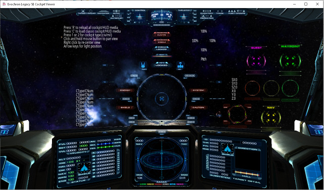
The Evochron Legacy Cockpit Viewer (ECV) is a small utility designed to help make the process of creating and modifying custom cockpits much easier. Rather than loading the game each time you want to test changes or additions to a custom cockpit design, the ECV program will render your design in a window with the ability to display animation sequences for indicators that support it as well as provide the ability to pan the view around with the mouse. It also lets you quickly reload your cockpit designs after you make changes. The program supports both custom cockpit indexes for testing, civilian (ccpit1.x) and military (ccpit2.x). With this program, you can edit the files associated with your custom cockpit, then quickly reload the files in the program to view the results at the same time. Once finished, you can import them into the game using the specified folder(s) and filenames. The program will load your custom cockpit files from the '\media\hud' folder inside the install folder. If no custom cockpit files are present, you'll generally receive an error message or see blank white surfaces in the window. Be careful when extracting this program from its ZIP since it contains a '\hud' folder with example files. If you already have a '\hud' folder in place, be sure to back up any files you have in that folder before extracting this program's '\hud' folder to the install folder. You can also optionally just extract the EvochronLegacySE-CockpitViewer.exe program from the ZIP if you already have the files you need in the '\hud' folder and/or don't need the example files. The program comes with the two default cockpit designs you can use as examples for how to set up a test for the viewing program. You'll need to include the various custom HUD image files and cockpit image/mesh files included in the ZIP to provide the minimum needed data for the program to display a custom cockpit design. That includes the high resolution versions of the texture files you're working with for your design (ccpitX-high.png, ccpitXglass-high.png, ccpitXnormal-high.png, ccpitXshader-high.png where X is either 1 or 2 for the civilian or military design). You can later include the very high, medium, and low resolution versions when you're finished and ready to use the custom cockpit in the game. You only need the 'high' resolution version for this program. Certain text files specifying spacing and positioning are optional and are not included in the ZIP file. So only the minimum files needed are included in the ZIP file (some of which have been reduced in resolution and gray scaled). Consult with the game's online documentation for customizing below for more information on what each of the files is for. When you start the program, it will load what it is able to find in the '\media\hud' folder and display the cockpit in a 1280X720 window. You can optionally specify a custom window size by creating a text file in the game's install folder named ecvscreen.txt and include the horizontal resolution you want to use in the first line and the vertical resolution you want to use in the second line. Once the program has started and displays the custom cockpit, you can pan the view around by holding down the mouse button, then moving the mouse. The viewpoint will rotate based on the mouse cursor's distance from the middle of the window. Release the mouse button to stop panning the view. Click the right mouse button to re-center the view. When you want to reload the cockpit data (for example, after making changes to the design's files), press the 'R' key. Press the arrow keys to change the direction light is projected onto the cockpit (up for light from in front, down for light from behind, left for light from left, and right for light from right). If you want to switch between the two cockpit modes, press '1' for the civilian design, and '2' for the military design. You can later rename your custom cockpit files as desired later on. For the program, you'll need to use the main \hud folder and the ccpit1.x and ccpit2.x base mesh format. Here is the download link for the program: http://www.starwraith.com/evochronlegacy/customkitse/EvochronLegacySE-CockpitViewer.zip To customize the Heads-Up-Display and cockpit textures, use a directory name of '\hud' inside the '\media' folder and use the following file names for each aspect of the HUD/cockpit you want to modify. The included black-and-white sample images will help with positioning so the displays and indicators still look right and function correctly. You can also use higher resolution textures for more detail, if desired. You can also optionally provide certain images that are specific to a particular frame type (using the same frame index numbers listed in the previous section). To do this, the '\hud' folder must contain the frame index number after the 'hud' characters and the 'gauges.txt' file needs to be included in the frame specific folder. So for example, '\hud21' would include files for the Pulsar's specific cockpit (a list of each frame's index value is provided below in the Custom Cockpit Options section). Some image files are global and still need to be included in a base '\hud' folder, but many that are more cockpit specific can be uniquely applied to specific frame types. Global files that require the '\hud' folder are indicated below with '(Global)' after their listing. Filenames for HUD textures (PNG is default, GIF is also supported as an optional format, some limitations may apply with formatting): b2-compass.png = transparent compass and console buttons b2-compassshadow.png = compass shadow (inverse transparency, white is invisible) b2console.png = base console display b2console2.png = navigation console display b2consolebuild.png = build console display b2consoleinv.png = inventory console display b2consoleinv2.png = inventory console display (highlighted equipment and commodity description) b2consoleslide.png = navigation console for slide and 3D map modes b2consoletrade.png = trade console display b2console-shadow.png = shadow for console menu b2consolebuild-shadow.png = shadow for build console menu b2gun.png = transparent gunsight, mode 1 b2gun2.png = transparent gunsight, mode 2 b2gunshadow.png = gunsight shadow texture (inverse transparency, white is invisible), mode 1 b2gunshadow2.png = gunsight shadow texture, mode 2 b2gunwalker.png = terrain walker gunsight (Global) b2gunwalkershadow.png = terrain walker gunsight shadow texture (Global) b2gunwalker2.png = terrain walker radar display frame (Global) b2gunwalker3.png = terrain walker compass display frame (Global) b2gunwalker4.png = terrain walker side display frames (Global) b2light1.png = Mouseover highlight for Target, Order, Deploy, and Build HUD button options b2light2.png = Mouseover highlight for Navigation console and Inventory console HUD button options b2light3.png = Mouseover highlight for Jump Drive and Trade console HUD button options b2light4.png = Mouseover highlight for Autopilot HUD button option b2light5.png = Mouseover highlight for Formation HUD button option b2lineX.png = circular bar graphs around the gunsight (X = 1-10 for first group, 11-20 for second group) b2shield1.png = gunsight shield indicator (green) b2shield2.png = gunsight shield indicator (yellow) b2shield3.png = gunsight shield indicator (red) b2shieldimpact.png = gunsight shield array impact direction indicator blue-circle1.png = station radar blip, long range blue-circle2.png = station radar blip, medium range blue-circle3.png = station radar blip, close range blue-line1.png = station radar blip elevation buttonclose.png = Console close button buttonclose2.png = Console close button mouseover highlight ccpitblue1.png = 3D radar display screen texture (DIR/3D mode) ccpitblue1b.png = 2D radar display screen texture (DIS/2D mode) ccpitblue1c.png = 3D radar display galactic ecliptic surface (DIR/3D mode) ccpitblue1-colors.png = radar blip colors for each contact type ccpitblue2.png = ship status display screen texture (left) ccpitblue3.png = target status display screen texture (right) ccpitblue3b.png = target range list display screen texture (right) chatbarleft.png = text message area vertical bar chatbarline.png = text message area horizontal line highlight bar chatbarlineshadow.png = shadow for text message area chatbartop.png = text message area horizontal bar chatbox.png = blank button box chatclose.png = text message area close button chatcolors.png = color selection for text chat chatdown.png = text message area line down button chatdownb.png = mouseover text message area line down button chatdown2.png = text message area page down button chatdown2b.png = mouseover text message area page down button chatslider.png = text message area scroll box chatslider2.png = text message area scroll box active chatsliderbutton.png = text message area scroll button chatslidersmall.png = small scroll box chatslidersmall2.png = small scroll box active chattext.png = text chat mode button chattextb.png = mouseover text chat mode button chatup.png = text message area line up button chatupb.png = mouseover text message area line up button chatup2.png = text message area page up button chatup2b.png = mouseover text message area page up button compass.png = transparent numbers for compass display display-icon-capital#.png = (# = 1-6 for capital type: transport, destroyer, cruiser, battleship, command, carrier) display-icon-capitalvonari1.png = vonari capital ship icon display-icon-engine#.png = (# = 1-10 for each engine type) display-icon-frame#.png = (# = 1-10 [ALC], 11-13 [VON], 21-32 [MIL], 41-50 [FDN] for each frame type) display-icon-object#.png = (# = 1-5 for object type: cargo, modules/comet/asteroid, unknown, item/pod, scenery) display-icon-wings#.png = (# = 1-13 for each wing type) green1.png = bright green radar blip green2.png = medium green radar blip green3.png = station radar blip greenarrow.png = nav map direction indicator greenbox.png = nav map waypoint indicator green-circle1.png = friendly threat level radar blip, long range green-circle2.png = friendly threat level radar blip, medium range green-circle3.png = friendly threat level radar blip, close range green-line1.png = friendly threat level radar blip elevation grid.png = transparent sphere lines for 3D radar sphere and target ship direction indicator grid-horizon.png = transparent horizon surface for 3D radar sphere and target ship direction indicator grid-small.png = MFD transition effect texture heat.png = heat signature indicator heatshadow.png = heat signature indicator shadow hud1.png = target MFD range list left bracket hud1b.png = target MFD range list right bracket hud3.png = status display shield hull damage green bar hud3b.png = target MFD detail hull damage indicator bracket hud4.png = status display primary weapon energy indicator blue bar hud5.png = inbound missile range indicator red bar (kept for potential legacy use) hud7.png = target MFD detail hull damage indicator red bar hud8.png = red dot used for critical shield array level hud9.png = yellow dot used for critical shield array level hud10.png = green dot used for critical shield array level hud-alert1-X.png = transparent ENERGY alert indicator (X = 1-10 for each frame of animation) hud-alert2-X.png = transparent SHIELD alert indicator (X = 1-10 for each frame of animation) hud-alert3-X.png = transparent SYSTEM alert indicator (X = 1-10 for each frame of animation) hud-alert4-X.png = transparent CAUTION alert indicator (X = 1-10 for each frame of animation) hud-alert1-shadow.png = ENERGY alert indicator shadow texture hud-alert2-shadow.png = SHIELD alert indicator shadow texture hud-alert3-shadow.png = SYSTEM alert indicator shadow texture hud-alert4-shadow.png = CAUTION alert indicator shadow texture hudbox1.png = green ship pathway indicator hudbox2.png = yellow ship pathway indicator hudbox3.png = red ship pathway indicator hud-motion.png = tunnel motion indicators hud-motion2.png = spear motion indicators hudrings.png = race course rings hud-shipicon.png = ship control and thruster indicator icon for primary data hud-shipicon2.png = ship control and thruster indicator icon for secondary data hudtape.png = transparent numbers and lines for pitch ladder (single structure mode) hudtape-shadow.png = shadow for pitch ladder (single structure mode) hudtape-left.png = transparent numbers and lines for left side of pitch ladder (double structure mode) hudtape-left-shadow.png = shadow for left side of pitch ladder (double structure mode) hudtape-right.png = transparent numbers and lines for right side of pitch ladder (double structure mode) hudtape-right-shadow.png = shadow for left side of pitch ladder (double structure mode) icon-ast1.png = rocky asteroid nav map icon (Global) icon-ast2.png = ice asteroid nav map icon (Global) icon-ast3.png = metallic asteroid nav map icon (Global) icon-blackhole.png = black hole nav map icon (Global) icon-blue.png = map log entry nav map icon (Global) icon-carr.png = carrier nav map icon (Global) icon-cave.png = cave nav map icon (Global) icon-circle180b.png = short range sensor probe indicator (Global) icon-circle300b.png = long range sensor array indicator (Global) icon-city1.png = primary city nav map icon (Global) icon-city2.png = secondary city nav map icon (Global) icon-csta.png = constructor station nav map icon (Global) icon-gat.png = gate nav map icon (Global) icon-map.png = nav map background map grid (Global) icon-ping.png = ping nav map icon (Global) icon-sta1.png = station nav map icon (Global) icon-waypoint.png = waypoint area nav map icon (Global) icon-wor.png = wormhole nav map icon (Global) incominggunfire-X.png = incoming gunfire alert indicator (X = 1-10 for each frame of animation) incominggunfire-shadow.png = shadow for incoming gunfire alert indicator indicatorshadow.png = shadow for text alerts around gunsight (will be rotated 90 degrees and offset to center) inertial0.png = 'IDS OFF' indicator inertial1-X.png = 'IDS X#' indicator (X = 1-9 when IDS is active, '#' displays scale factor) inertial2.png = 'INERT' indicator (when in inertial mode) jettisonbutton1.png = jettison button jettisonbutton1b.png = jettison verification button jettisonbutton2.png = mouseover jettision button jettisonbutton2b.png = mouseover jettision verification button landblue1.png = cargo delivery point path landblue2.png = cargo delivery point path landgreen1.png = ILS green landing path landgreen2.png = ILS green landing path landred1.png = ILS red landing path landred2.png = ILS red landing path landshadow.png = ILS landing path shadow map.png = Quadrant map (Global) mapt.png = Territory quadrant map (Global) mape.png = Economy quadrant map (Global) mdts0.png = transparent MDTS off indicator mdts1.png = transparent MDTS active indicator mdts2-X.png = transparent MDTS tracking indicator (X = 1-10 for each frame of animation) mdtsshadow.png = MDTS indicator shadow menu4.png = small menu frame for certain alerts mi-X.png = transparent missile inbound alert indicator (X = 1-10 for each frame of animation) mi-shadow.png = shadow for inbound alert indicator mi2.png = bright yellow inbound missile highlight box mlock1-X.png = transparent missile lock indicator (X = 1-10 for each frame of animation) mlockmode1.png = missile lock mode one (active guidance) indicator on ship status display mlockmode2.png = missile lock mode two (retain target) indicator on ship status display mlock-shadow.png = shadow for missile lock indicator mode1.png = particle and beam weapon firing mode indicator mode2.png = particle weapon firing mode indicator mode3.png = beam weapon firing mode indicator modeshadow.png = firing mode indicator shadow navmapgreen1.png = ALC quadrant map region territory control indicator (default zoom) navmapgreen2.png = ALC quadrant map region territory control indicator (zoomed mode) navmappurple1.png = vonari quadrant map region territory control indicator (default zoom) navmappurple2.png = vonari quadrant map region territory control indicator (zoomed mode) navmapred1.png = FDN quadrant map region territory control indicator (default zoom) navmapred2.png = FDN quadrant map region territory control indicator (zoomed mode) navmapyellow1.png = disputed quadrant map region territory control indicator (default zoom) navmapyellow2.png = disputed quadrant map region territory control indicator (zoomed mode) point1.png = menu selection mode mouse pointer point1-shadow.png = menu selection mode mouse pointer shadow point4.png = flight mode mouse pointer point4console.png = selection mode mouse pointer point4cshadow.png = selection mode mouse pointer shadow point4shadow.png = flight mode mouse pointer shadow point8.png = nav map selection mode mouse pointer point8shadow.png = nav map selection mode mouse pointer shadow purple1.png = cargo/weapon storage container and wormhole radar blip purplebox.png = purple quest radar and nav map indicator purple-circle1.png = miscellaneous/unknown object radar blip, long range purple-circle2.png = miscellaneous/unknown object radar blip, medium range purple-circle3.png = miscellaneous/unknown object radar blip, close range purple-line1.png = miscellaneous/unknown object radar blip elevation red.png = red coloring used for target display critical damage level red1.png = dim red radar blip red2.png = medium red radar blip red3.png = bright red radar blip redbox2.png = red highlight box red-circle1.png = hostile threat level radar blip, long range red-circle2.png = hostile threat level radar blip, medium range red-circle3.png = hostile threat level radar blip, close range red-line1.png = hostile threat level radar blip elevation strafe.png = transparent strafe indicator (flight path marker and horizontal/vertical velocity marker) strafe2.png = optional texture option for horizontal/vertical velocity marker strafeshadow.png = strafe indicator shadow strafe2shadow.png = optional texture option for horiztonal/vertical velocity marker shadow target1.png = red lead indicator target1green.png = green lead indicator target1yellow.png = yellow lead indicator target2.png = red tracking indicator high priority target3.png = red tracking indicator for target target3green.png = green tracking indicator for target target3green-fleet.png = green tracking indicator for fleet target target3yellow.png = yellow tracking indicator for target target4.png = red tracking indicator target4b.png = red missile lock indicator target5.png = red direction pointer target5blue.png = blue direction pointer target5yellow.png = yellow direction pointer target5green.png = green direction pointer target7.png = green tracking indicator target7-fleet.png = green fleet ship tracking indicator target7b.png = green missile lock indicator target8.png = yellow tracking indicator target8b.png = yellow missile lock indicator target9.png = white highlight direction and range indicator for nearest cargo target10.png = blue station tracking indicator target11.png = asteroid indicator target12.png = secondary direction indicator for cargo target18.png = blue tracking indicator for objects target18b.png = blue missile lock indicator target-shield1.png = green shield indicator target-shield2.png = yellow shield indicator target-shield3.png = red shield indicator targetmissile2.png = HUD pointer range bar for inbound missiles, regular threat level targetmissile2red.png = HUD pointer range bar for inbound missiles, critical threat level targetmissile3.png = HUD pointer and range bracket for inbound missiles, regular threat level targetmissile3red.png = HUD pointer and range bracket for inbound missiles, regular threat level targetradarblue.png = blue target highlight radar blip targetradargreen.png = green target highlight radar blip targetradarmissile.png = inbound missile blip targetradarred.png = red target highlight radar blip targetradaryellow.png = yellow target highlight radar blip targetshadow.png = tracking indicator shadow for target targetshadow-fleet.png = tracking indicator shadow for fleet target targetshadow2.png = tracking indicator shadow targetshadow2-fleet.png = tracking indicator shadow for fleet ship targetshadow2b.png = missile lock indicator shadow targetshadow3.png = shadow for navigation direction and range indicator targetshadow4.png = inbound missile indicator shadow targetshadow5.png = lead indicator shadow targetshadow7.png = mouse pointer shadow targetshadow8.png = shadow for waypoint direction and range indicator targetshadow9.png = shadow for direction and range indicator for nearest cargo targetshadow10.png = shadow for station tracking indicator targetshadow12.png = shadow for secondary direction indicator for cargo targetshadow18.png = shadow for quest direction and range indicator view-abovecamera.png = text for 'Above Camera View' label. view-left.png = text for 'Left View' label. view-mouselook.png = text for 'Mouse Look' label. view-padlock.png = text for 'Padlock View' label. view-rearcamera.png = text for 'Rear Camera View' label. view-right.png = text for 'Right View' label. waypoint1.png = green waypoint direction and range indicator waypointn.png = yellow navigation direction and range indicator waypointq.png = purple quest direction and range indicator white.png = white radar blip white-circle1.png = cargo radar blip, long range white-circle2.png = cargo radar blip, medium range white-circle3.png = cargo radar blip, close range white-line1.png = cargo radar blip elevation yellow.png = yellow coloring used for target display moderate damage level yellow1.png = bright yellow radar blip yellow-missile.png = medium yellow radar blip for inbound missiles yellowbox.png = yellow navigation radar and nav map indicator yellow-circle1.png = moderate threat level radar blip, long range yellow-circle2.png = moderate threat level radar blip, medium range yellow-circle3.png = moderate threat level radar blip, close range yellow-line1.png = moderate threat level radar blip elevation If any specified PNG images have been replaced with GIF images that use animation, you can enable the custom image animation mode by creating a file named 'animationimagemode.txt' and in the first line, enter the number 1, then save the file in the same '\hud' folder that the custom animated GIF images are located in. If the file is not included or the value in the first line is set to 0, then only the first frame of any animated GIF will appear. You can optionally include a second line in the file to enable or disable the internal animation sequence for the HUD alert, inbound gunfire, inbound missile, MDTS lock, and missile lock indicators. Set the value to 0 for the default internal animation sequence which uses 10 frames of animation via files specified above for each indicator. Set the value to 1 to disable the internal animation so you can import custom GIF image files with their own animation sequences. When the internal animation is disabled, then only the first image in an animation sequence will be loaded so a single GIF image can be applied. Here is a list of each of the individual image files that will be loaded for each indicator: MDTS Lock Indicator = mdts2-1.gif Missile Lock Indicator = mlock1-1.gif Incoming Missile Indicator = mi-1.gif Incoming Gunfire Indicator = incominggunfire-1.gif Energy HUD Alert = hud-alert1-1.gif Shield HUD Alert = hud-alert2-1.gif System HUD Alert = hud-alert3-1.gif Caution HUD Alert = hud-alert4-1.gif Other non-animation images that may apply for certain indicators will remain the same. Custom Cockpit Options: Like custom HUD options above, the '\hud' folder location is also used for custom cockpit files. You can use the base '\hud' folder location inside the '\media' folder for globally applying custom files. Or you can add a frame's index value after the '\hud' folder name to apply changes to a specific ship type. Here is a list of the various frame types in the game along with their respective index values (note: the ship frame indexes are +1 in value relative to certain filenames for each, so the first Talon frame starts at index 1): Alliance: 1 = Talon 2 = Osprey 3 = Saber 4 = Falcon 5 = Raptor 6 = Phoenix 7 = Eagle 8 = Renegade 9 = Centurion 10 = Leviathan Federation: 41 = Arrow 42 = Scorpion 43 = Hunter 44 = Typhoon 45 = Venture 46 = Sentinel 47 = Guardian 48 = Paladin 49 = Titan 50 = Starmaster Military: 21 = Pulsar 22 = Razor 23 = Shadow 24 = Wraith 25 = Evoch 26 = Nighthawk 27 = Lamprey 28 = Firestar 29 = Avenger 30 = Shrike 31 = Predator 32 = Chimera The custom cockpit options are available through two different systems. The first system lets you customize the existing cockpit structures and textures. This way, you can remove or change details within the existing cockpit framework, rather than having to import an entirely unique structure and texture set. For the first custom cockpit option, these three object files are needed (OBJ format files can optionally be used): ccpit#.x = base cockpit structure mesh (include textures in the same folder) ccpit#displays.x = cockpit displays (the frames/screens that project the holographic display details) ccpit#glass.x = cockpit glass surface (rendered transparent and reactive to scene lighting) Custom joystick and throttle objects can also be included (OBJ format files can optionally be used): ccpit-joystick.x = joystick object ccpit-throttle.x = throttle object There are also the texture files below. The first set of files is for the two primary cockpits, the second set is for additional cockpit designs introduced in version 2.0308. The files you'll need to replace will be determined by which ship frame's cockpits you are replacing and which mode you are using. Here are the texture filenames: Original file set (indexes 1 and 2): ccpit#-[detail].png = Base texture map ccpit#normal-[detail].png = Normal map ccpit#shader-[detail].png = Specular map ccpit#lights-[detail].png = Emissive map ccpit#glass-[detail].png = Glass texture Added file set for newer designs (above index 2): ccpitb#-[detail].png = Base texture map ccpitb#normal-[detail].png = Normal map ccpitb#shader-[detail].png = Specular map ccpitb#lights-[detail].png = Emissive map ccpitb#glass-[detail].png = Glass texture The '#' character will either be a 1 for the civilian cockpit or a 2 for the military cockpit for mode 0. The '#' will be a value from 1 to 9 for the expanded mode, with the original two cockpit designs and options using indexes 1 and 2 with the newer designs and options using indexes 3 through 9. This way, you can import custom cockpit structures and/or textures in part or in whole using the game's loading mechanism for the default cockpits. Simply include the desired file(s) in the \hud folder for the object and/or texture structure you wish to replace. Replace [detail] with each level of optional detail starting with 'low', then 'medium', 'high', then finally 'veryhigh'. Higher resolutions will require more memory in exchange for a more detailed look. To specify an optional custom detail texture for cockpits, use this filename (the UV scaling level can optionally be adjusted with the 'ccpitlight.txt' settings file detailed belowm default scaling is 8): normalspec-detail5.png You can optionally limit the number of cockpit indexes used by the game to the original two by creating a text file named 'ccpitmode.txt' in either '\media' folder or the save data folder and in the first line, enter either a 0 to limit the indexes to original two or a 1 to enable the expanded range of optional cockpit indexes. If no 'ccpitmode.txt' file is in place, the game will default to the expanded mode for all available cockpit indexes. You can also optionally add a value in the second line to specify a cockpit index you want to use regardless of what ship you fly. Available indexes range from 1 to 9. 1 and 2 represent the original cockpit designs for the civilian and military range of ships respectively. Indexes 3 through 9 represent the newer cockpit designs added later. You can also specify a single object file on its own for all of the primary cockpit structures. This option is best if you want to use one global cockpit object for the entire game. Simply include the object file named 'ccpit.x' in the \hud folder. You can also optionally include an additional object for the cockpit's glass named 'ccpitglass.x' which will be rendered transparent and reactive to scene lighting. Once you've imported the structure, you will need to also include a 'ccpitshader.txt' file in the same \hud folder that specifies the textures you want to use for a base map, normal map, and specular map. Here is the required layout for this file: ccpitshader.txt 1st value specifies the base map (exact filename, place file in \hud folder) 2nd value specifies the normal map (exact filename, place file in \hud folder) 3rd value specifies the specular map (exact filename, place file in \hud folder) 4th value specifies the emissive map (exact filename, place file in \hud folder) 5th value specifies the glass texture (exact filename, place file in \hud folder) For both custom cockpit systems (frame specific or global), you can also specify a custom cockpit for each ship individually by adding the frame number to the end of the \hud folder in its name. For example, if you wanted to specify a custom cockpit for the Talon in the game, simply add the number 1 to the end of the \hud folder so it reads \hud1. This way, the custom cockpit will apply only for that ship type and not the others. In the default expanded cockpit mode, each index can apply to one or more ship frame types. Some ship frames share similar/related designs, so they also share the same cockpit index. Here is a list of each frame type and its cockpit index which can be used to customize a cockpit for a specific ship based on shared indexes (you can also specify a custom cockpit design for each ship individually using the 'hud#' folder option mentioned earlier, this list is just for replacing cockpit structures for ships by their linked index groups): Talon = Index 1 Osprey = Index 4 Saber = Index 3 Falcon = Index 8 Raptor = Index 7 Phoenix = Index 7 Eagle = Index 8 Renegade = Index 4 Centurion = Index 5 Leviathan = Index 5 Arrow = Index 3 Scorpion = Index 1 Hunter = Index 4 Typhoon = Index 5 Venture = Index 8 Sentinel = Index 8 Guardian = Index 4 Paladin = Index 4 Titan = Index 1 Starmaster = Index 1 Pulsar = Index 2 Razor = Index 2 Shadow = Index 2 Wraith = Index 2 Evoch = Index 6 Nighthawk = Index 6 Lamprey = Index 6 Firestar = Index 2 Avenger = Index 2 Shrike = Index 2 Predator = Index 6 Chimera = Index 9 To change the soft light glowing effect reflected on cockpit surfaces by the HUD and displays, create a text file named 'ccpitlight.txt' in the '\hud' folder and use the following values: ccpitlight.txt 1st value specifies the red color value of the light (range 0-1.0, default value 0.1) 2nd value specifies the green color value of the light (range 0-1.0, default value 0.4) 3rd value specifies the blue color value of the light (range 0-1.0, default value 0.5) 4th value specifies the X position of the light (default value 0) 5th value specifies the Y position of the light (default value 0.5) 6th value specifies the Z position of the light (default value 1.5) 7th value specifies the range of the light (default value 10.0) 8th value specified the UV scaling for the optional detail texture (default 8) Optional location data for HUD control and thruster indicators (also uses the \hud folder): huddisplays.dat 1st pitch yaw X location (default value is -2.59) 2nd pitch yaw Y location (default value is 7.08) 3rd pitch yaw Z location (default value is 0) 4th strafe X location (default value is -2.59) 5th strafe Y location (default value is 6.52) 6th strafe Z location (default value is 0) 7th roll X location (default value is -1.858) 8th roll Y location (default value is 6.32) 9th roll Z location (default value is 0) 10th front thrusters X location (default value is 2.59) 11th front thrusters Y location (default value is 7.08) 12th front thrusters Z location (default value is 0) 13th rear thrusters X location (default value is 2.59) 14th rear thrusters Y location (default value is 6.52) 15th rear thrusters Z location (default value is 0) 16th engine X location (default value is 1.858) 17th engine Y location (default value is 6.32) 18th engine Z location (default value is 0) 19th control displays ship icon X location (default value is -1.8) 20th control displays ship icon Y location (default value is 6.8) 21st control displays ship icon Z location (default value is 0) 22nd thruster displays ship icon X location (default value is 1.8) 23rd thruster displays ship icon Y location (default value is 6.8) 24th thruster displays ship icon Z location (default value is 0) 25th global scale factor (default value is 15.0) The default color of chat/message text in the message log is white-blue by default. You can change this by using a text file named chattext.dat to make it stand out more in contrast to white system message text. Color options apply to the default color values only. Players are still able to select custom text colors in the multiplayer mode for their sent messages. You can also change the location of the text chat/message log. It is recommended that you do not change the pixel offset values or the Y position value, unless other mods you have need special adjustments. If you move the message log to the left using negative values for the X position, the mouse pointer will automatically toggle to the control buttons and slider on the left side of the log when you move the pointer to the left edge of the screen. Then when you move it away from the control buttons and slider, it will return to the main central area of the screen. chattext.dat 1st value sets the red color (0-255, default 100) 2nd value sets the green color (0-255, default 255) 3rd value sets the blue color (0-255, default 255) 4th value sets the X pixel offset (usually leave at 20) 5th value sets the Y pixel offset (usually leave at 50) 6th value sets the X position (ie -7.5 for widescreen displays) 7th value sets the Y position (usually leave at 0) Optional 3D gauge/display positions and appearance (used to accomodate custom cockpits): gauges.txt 1st value sets the left display's vertical position, default is -0.1 2nd value sets the left display's horizontal position, default is 0.68 3rd value sets the left display's Y rotation angle, default is -20 4th value sets the center display's vertical position, default is -0.25 5th value sets the center display's horizontal position, default is 0.0 6th value sets the center display's Y rotation angle, default is 0 7th value sets the right display's vertical position, default is -0.1 8th value sets the right display's horizontal position, default is -0.68 9th value sets the right display's Y rotation angle, default is 20 10th value sets the target object's vertical position, default is 2.5 11th value sets the target object's horizontal position, default is 2.88 12th value sets the 3D radar sphere's vertical position, default is -0.08 13th value sets the 3D radar sphere's horizontal position, default is 0.0 14th value sets the left display's distance, default is 0.0 15th value sets the center display's distance, default is 0.0 16th value sets the right display's distance, default is 0.0 17th value sets the target object's distance, default is 0.08 18th value sets the 3D radar sphere's distance, default is 0.0 19th value sets the 3D radar sphere display's shadow horizontal position, default is 0.0 20th value sets the 3D radar sphere display's shadow vertical position, default is -0.12 21st value sets the 3D radar sphere display's shadow distance position, default is 0.0 22nd value sets the left display's shadow horizontal position, default is -0.07 23rd value sets the left display's shadow vertical position, default is -0.09 24th value sets the left display's shadow distance position, default is 0.0 25th value sets the right display's shadow horizontal position, default is 0.07 26th value sets the right display's shadow vertical position, default is -0.09 27th value sets the right display's shadow distance position, default is 0.0 28th value sets the 3D radar sphere's size factor, default is 1.34 29th value sets the left display's X size factor, default is 1.25 30th value sets the left display's Y size factor, default is 1.25 31st value sets the center display's X size factor, default is 1.25 32nd value sets the center display's Y size factor, default is 1.25 33rd value sets the right display's X size factor, default is 1.25 34th value sets the right display's Y size factor, default is 1.25 35th value sets the target direction indicator scale factor, default is 0.011 36th value sets the bar graph mode, 0 = 2D, 1 = 3D, 2 = 3D with background hologram layers, default is 0 37th value sets the radar blip vertical offset factor, default is 0.0345 38th value sets the flight path marker texture offset factor, default is -0.01 39th value sets the gunsight front shield indicator X offset, default is 0 40th value sets the gunsight front shield indicator Y offset, default is -0.02 41st value sets the gunsight right shield indicator X offset, default is -0.015 42nd value sets the gunsight right shield indicator Y offset, default is -0.0075 43rd value sets the gunsight rear shield indicator X offset, default is 0 44th value sets the gunsight rear shield indicator Y offset, default is 0.005 45th value sets the gunsight left shield indicator X offset, default is 0.015 46th value sets the gunsight left shield indicator Y offset, default is -0.0075 47th value sets the radar nav readout X offset, default is -0.05 48th value sets the radar nav readout Y offset, default is 0 49th value sets the radar thc readout X offset, default is 0.1 50th value sets the radar thc readout Y offset, default is 0 51st value sets the radar mod readout X offset, default is 0.1 52nd value sets the radar mod readout Y offset, default is 0 53rd value sets the radar rng readout X offset, default is -0.1 54th value sets the radar rng readout Y offset, default is 0 55th value sets the flight path marker size, default 1.0 56th value sets the left display's X rotation angle, default is 0 57th value sets the left display's Z rotation angle, default is 0 58th value sets the center display's X rotation angle, default is 0 59th value sets the center display's Z rotation angle, default is 0 60th value sets the right display's X rotation angle, default is 0 61th value sets the right display's Z rotation angle, default is 0 62nd value sets the radar horizon's X rotation angle, default is 88.0 63rd value sets the radar horizon's Y rotation angle, default is 0 64th value sets the radar horizon's Z rotation angle, default is 0 When the bar graph mode option is set to mode 1 or 2, an alternate set of textures is recommended to better support the 3D structure of the bar graph indicators. A sample image set is available here: (these images need to be placed in the '\hud' folder within the '\media' folder to apply) Optional location positions for the HUD flight timer, center gunsight text readouts, and digital compass as well as overall character size: hudtext.txt 1st value sets the timer's horizontal position 2nd value sets the timer's vertical position (offset from the default location) 3rd value sets the timer's distance position (offset from the default location) 4th value sets the center gunsight's text readouts horizontal position 5th value sets the center gunsight's text readouts vertical position 6th value sets the overall character size value for the display text 7th value sets the digital compass indicator's horizontal position 8th value sets the digital compass indicator's vertical position 9th value sets the digital compass indicator's distance position 10th value sets the character size value for the HUD secondary direction indicators 11th value sets the character size value for the HUD target direction indicator 12th value activates the HUD bar graphs (0 = off, 1 = on) 13th value sets the character spacing value for HUD and display characters (default 0.84 for Small font size setting, 0.92 for Medium, and 1.0 for Large) 14th value sets the secondary scale offset value (applied after font size adjustments) 15th value sets the scale level for alert, heat level, primary weapon firing mode, and IDS indicators 16th sets the position for the VVL readout arrow (0 = left, 1 = HUD right, 2 = all right) 17th sets the position for the HVL readout arrow (0 = left, 1 = HUD right, 2 = all right) You can change the location of the gunsight primary weapon firing mode and IDS mode indicators (visible in HUD mode 2) the following file and values: modeindicators.txt 1st value sets the weapon firing mode indicator's horizontal position (default 0) 2nd value sets the weapon firing mode indicator's vertical position (default 0) 3rd value sets the IDS mode indicator's horizontal position (default 0) 4th value sets the IDS mode indicator's vertical position (default 0) You can change the location, size, and color of the gunsight IDS input mode character (visible in HUD mode 2) to accommodate custom status images with the following file and values: hudinertialinput.txt 1st value sets the character's horizontal position (default 0.525) 2nd value sets the character's vertical position (default 1.235) 3rd value sets the character's size factor (default 1.4) 4th value sets the character's baseline color (default 100 for white, see values below) 5th value sets the character's mode (0 for mode setting, 1 for IDS scale factor) 6th value sets the red offset for coloring (default 0.7254) 7th value sets the green offset for coloring (default 0.898) 8th value sets the blue offset for coloring (default 1.0) Here are other color values available for the IDS input mode character: 100 = White 400 = Gray 700 = Dim Gray 1100 = Bright Red 1400 = Medium Red 1700 = Dim Red 2100 = Bright Green 2400 = Medium Green 2700 = Dim Green 3100 = Bright Blue 3400 = Medium Blue 3700 = Dim Blue 4100 = Bright Purple 4400 = Medium Purple 4700 = Dim Purple 5100 = Bright Cyan 5400 = Medium Cyan 5700 = Dim Cyan 6100 = Bright Yellow 6400 = Medium Yellow 6700 = Dim Yellow You can change the movement rate of the HUD motion spear indicators with the following file and values. Note: this file either needs to be created manually in the save data folder or the player needs to select the 'Spears' mode in the Options > 3D Cockpit menu before the file will be present. Changing the motion indicator mode in the 3D Cockpit menu will reset the rate parameter to the default 0.5 value. hudmotion.txt 1st value sets the movement indicator mode (0 = tunnel, 1 = spears, 2 = none) 2nd value sets the spear indicator movement rate (default 0.5) 3rd value sets the spacing maximum for all spears (default 1.0) 4th value sets the scaling for motion indicators (default 1.0) 5th value sets the lock direction mode for the tunnel (0 = no lock, 1 = lock direction, 2 = rotate 45 degrees, 3 = rotate 45 degrees and lock direction) 6th value sets the depth mode (0 = no depth, 1 = depth relative to scene structures and scaling) 7th value sets the spears rows mode (0 = 4 rows, 1 = 3 rows, 2 = 2 rows) Optional readouts for cargo bay, ship location, shield levels, and pitch level: hudtext.dat 1st value sets the activation value (should generally always be 1) 2nd value sets the red color level of the text (0-255) 3rd value sets the green color level of the text (0-255) 4th value sets the blue color level of the text (0-255) 5th value is no longer used and is a placeholder for possible future use 6th value sets the cargo readout's activation status (0 = off, 1 = on) 7th value sets the cargo readout's X position 8th value sets the cargo readout's Y position 9th value sets the location readout's activation status (0 = off, 1 = on) 10th value sets the location readout's X position 11th value sets the location readout's Y position 12th value sets the shield level readout's activation status/spacing (>0 = on and spacing) 13th value sets the shield level readout's X position 14th value sets the shield level readout's Y position 15th value sets the pitch level readout's activation status (0 = off, 1 = on) 16th value sets the pitch level readout's X position 17th value sets the pitch level readout's Y position Optional scaling for the HUD pitch ladder: pitchladder.txt 1st value sets the X scaling (default is 100) 2nd value sets the Y scaling (default is 100) 3rd value sets the structure mode (0 = single plane, 1 = default double plane) 4th value sets the left side tape (double plane only, default is -0.7) 5th value sets the right side tape (double plane only, default is 0.7) 6th value sets the horizontal stretch level (double plane only, default 0.15) If a 'hudtape.png' image file is detected in a '\hud' folder for a single plane pitch ladder, then the game will default to the single plane structure mode. HUD compass structure and position: compass.txt 1st value sets the X position (default is 0) 2nd value sets the Y position (default is 15.345) 3rd value sets the Z position (default is 27.9) 4th value sets the X scale factor (default is 1.0) 5th value sets the Y scale factor (default is 1.0) 6th value sets the Z scale factor (default is 1.0) 7th value sets mode (0 = default 3D cylinder, 1 = 2D tape limited values, 2 = 2D tape more values) Optional texture and surface scaling for the target direction pointer: targetpointer.txt 1st value sets the texture UV X scale (default value is 1.0) 2nd value sets the texture UV Y scale (default value is 1.0) 3rd value sets the texture UV X offset scale (default value is 0) 4th value sets the texture UV Y offset scale (default value is 0) 5th value sets the scaling percentage for the 3D surface (default value is 104.0) Optional scaling and angle positioning for the HUD gunsight circular bar graph readouts: hudbargraphs.txt 1st value sets the X distance from the center of the gunsight (default value is 1.55) 2nd value sets the Y distance from the center of the gunsight (default value is 1.45) 3rd value sets the Z depth distance from gunsight layer (default value is 0) 4th value sets the scale factor for bar graphs (default value is 0.84) 5th value sets the X distance from the center of the gunsight for shield indicators (default 0) 6th value sets the Y distance from the center of the gunsight for shield indicators (default 0) 7th value sets the Z depth distance from gunsight layer for shield indicators (default 0) 8th value sets the scale factor for shield indicators (default value is 1.0) The 'b2line#.png' images in the \hud folder are used for the circular bar graphs around the gunsight. Optional mode, rotation maximum, compass/pitch readout, and shadow values for the OCRS (Off-Center Readout System): ocrssettings.dat 1st value sets the default OCRS mode (0 = off, 1 = on) 2nd value sets the maximum pitch range for OCRS activation (default 20.0) 3rd value sets the maximum yaw range for OCRS activation (default 30.0) 4th value sets the digital compass and pitch readout status (0 = off, 1 = on) 5th value sets the shadow level (range 0-100) Optional positioning and movement range parameters for joystick and throttle: joystickthrottle.txt 1st value sets the X position of the joystick (default is 1.75) 2nd value sets the Y position of the joystick (default is 1.4) 3rd value sets the Z position of the joystick (default is -2.0) 4th value sets the movement range of the joystick (default is 0.025) 5th value sets the X position of the throttle (default is 1.75) 6th value sets the Y position of the throttle (default is 1.4) 7th value sets the Z position of the throttle (default is -2.2) 8th value sets the movement range of the throttle (default is 0.05) 9th value sets the joystick movement response (0 = yaw, 1 = roll) Optional camera shake and cockpit movement levels: You can adjust the level of camera impact shaking via an external text file option (create a file named 'shakelevel.txt' in the save data folder, default location is '\Documents\EvochronLegacySE'). The default value is 1.0 with a range of 0 to 10.0, which you can adjust up or down to whatever level of impact shake effect you want to apply. You can adjust the level of movement for cockpit structures with a text file named 'ccpitmove.txt' in either the save data folder ('\Documents\EvochronLegacySE') or the '\media' folder inside the game's installation folder and in the first line, enter a value for the level of movement. The default value is 1.0 and you can set it to 0.0 for no movement or a higher value for more movement. Optional global scaling for UI/HUD, cockpit, and camera range: You can optionally adjust the global scaling for the UI/HUD, cockpit along with the three holographic displays, and minimum camera range. These values can be adjusted to better accommodate custom cockpit designs as well as desired scaling for 3D rendering. You can bring in the HUD and other UI elements by reducing the scaling value, or move them out farther away with a higher value. Likewise, the cockpit can be independently scaled this way. And you can change the minimum camera range to minimize/eliminate clipping for structures that are very close to the player's viewpoint. Here are the available options: ccpithudscaling.txt 1st value sets the main HUD/UI scaling level (default is 0.35) 2nd value sets the cockpit and holographic display scaling (default is 0.8) 3rd value sets the minimum camera range (default is 1.0) 4th value sets the global HUD scaling factor (default is 0.01) Optional custom displays and indicators: The custom cockpit display and indicator system lets you add, place, scale, and rotate custom cockpit displays with information and/or images you choose to render on them. An example is included with the cockpit viewer program that places a custom display on top of one of the original default displays in the civilian design. You can use that example as a template to create your own custom displays. Up to 9 individual displays can be added with up to 9 indicators or readouts each (digital/text or bar graphs). You can include custom static images for reminders, notes, or just eye candy. Or you can use a static image to display background frames/labels for readouts/indicators rendered on top. You can then add individual indicators using either digital/text readouts or bar graphs to display various values related to ship systems. Some bar graph options will display on or off indicators, so you can make alert or status lights with those (including individual custom image options for the lights). Full position, scaling, and rotation options are available for both the base displays and their indicators. Indicators are automatically centered and aligned to their linked display and can be positioned, scaled, and rotated independently using their own set of values. For digital/text indicators, you can also set the spacing between individual characters. Instructions are included in the 'CustomDisplays.txt' configuration file included in the \media\hud folder with the cockpit viewing program. LinkApp display option: The Evochron Legacy SE LinkApp connects with an Android phone or tablet wirelessly (or by ethernet) over a local network to communicate with the game in order to display location, ship, and target details on the mobile device while playing the game. To use the app, first download and install it on the Android device using the APK available here (consult your device's documentation on side-loading apps): https://www.starwraith.com/evochronlegacy/customkitse/Evochron8-CompanionApp.apk Once the app is installed on the device you want to link to the game, enable the LinkApp option by checking the box next to 'Activate LinkApp' in the Options menu (Options > 3D Cockpit > Activate LinkApp). This will create a file named 'savedataapp.txt' located in the default save data folder (\Documents\EvochronLegacySE). You can optionally edit this file to change some of the parameters. The first line of the file will contain the update rate, which is how frequently the game will broadcast data to the mobile device in milliseconds. The range is from 100 to 1000 (higher is possible, but not generally recommended). Line two will let you select a custom port value for the connection (default is 29887), leave blank for the default value. Once you've made any desired changes, save the file and launch the game. Once you have finished the startup sequence in the game, this green message will be displayed in the message log: '< Connection established for LinkApp >' That message indicates the game successfully started the network connection to link to the app and will include the current IP address and port number of the connection which you will need for the app to connect with. Once that's done and the game is running, you can launch the LinkApp on the mobile device. It will first prompt you to enter the IP address to connect to the game with. Enter the address and tap '[ OK ]'. If successful, the app will advance to the default 'Location' mode and begin displaying data transmitted from the game. You can tap 'Ship Status' for readouts about your ship or 'Target Details' for readouts about your current target. To close the app, you'll need to bring up the exit button option in Android. Point menu system: A dedicated point menu system is available for the experimental VR mode, but it can also be enabled for standard display modes. To enable the point menu in a standard display mode, created a text file named 'pointmenu.txt' inside the '\media' folder and use the following lines for parameters: 1st value sets the menu mode (0 = off, 1 = passive - on when mouse pointer is visible, 2 = always on) 2nd value sets the X position of the left menu (default is 0) 3rd value sets the Y position of the left menu (default is 250) 4th value sets the X position of the right menu (default is 490) 5th value sets the Y position of the left menu (default is 250) You can also optionally apply a negative X position value to either menu to hide one. Station attack alert indicator: To change the station attack alert indicator, create a text file named 'stationattackdisplay.txt' inside the '\media\hud' folder and in the first line, apply one of the following values: 1st value sets the mode (0 = default, text description and animated lines, 1 = text only, 2 = off) Optional texture and surface scaling for the target direction indicator: targetshields.txt 1st value sets the spacing of the target direction indicator's shield bars (default value is 0.33) Missile lock fade effect: missilelockfade.txt 1st value sets the fade mode (0 = off/no fading, 1 = on, default) HUD Cycle Mode Options: To specify the HUD mode upon launching, the direction HUD modes cycle, and restrictions on available HUD modes, create a text file named 'hudcyclesettings.txt' in either the save data folder (\Documents\EvochronLegacySE) or the '\media' folder. You can then enter these lines to set values: LaunchHUD=2 HUDCycleD=1 HUDActive=0 The 'LaunchHUD' parameter will set the HUD mode when the game starts or when respawning. Set to either 1 for mode 1 or 2 for mode 2. The 'HUDCycleD' parameter will set the direction the HUD modes are cycled in. Set to 1 for increasing increments or -1 for decreasing increments. The 'HUDActive' parameter will select which HUD modes will be available/active in the range. Set to 0 to allow the full range of HUD modes that includes off, mode 1, and mode 2. Set to 1 to not allow turning off the HUD entirely, leaving only mode 1 and mode 2 available. Set to 2 to restrict the modes to off and mode 1. Set to 3 to restrict the modes to off and mode 2. Fleet Ship Characters: To specify custom fleet ship characters for direction indicators, target indicator, and cockpit MFD, create a text file named 'fleetshipcharacters.txt' in either the save data folder (\Documents\EvochronLegacySE) or the '\media' folder. Enter the left character in the first line and the right character in the second line. You can specify just a left character or you can also optionally leave out characters in both lines to remove all characters. Nav Map Asteroid Icon: The asteroid icon on the nav map can be changed in both structure and texture formatting. To change the icon mode, create a text file named 'roidiconmode.txt' in either the save data folder (\Documents\EvochronLegacySE) or the '\media' folder. In the first line, enter the number value for the desired mode. 0 is the default 3D structure with tiling/repeating texture, 1 is a flat 2D structure with tiling/repeating texture, and 2 is a flat 2D structure with non-tiling texture.
To customize the sound effects in the game, use a directory named \sounds and the following filenames: ambient.wav = ambient sound while player is in cockpit view (loops) ambient-base.wav = sound effect for entering/exiting station gates (loops) backg.wav = background mechanical hum for main menu if no music selected (loops) buzz.wav = error mouse click buzz buzz2.wav = inbound missile audio alert chaff.wav = countermeasures cruisedrive.wave = cruise drive (loops) dock.wav = docking effect exp-sound1.wav = missile explosion exp-sound2.wav = collision flak.wav = flak explosion sound flyby.wav = small ship fly-by effect (loops) flyby-capital.wav = capital ship fly-by effect (loops) gunX.wav = gunfire sound effects (X is the gun type number, 1-15, starting with 1 for the Banshee) hostilealert.wav = hostile ship in range alert laser.wav = laser sound effect lock1.wav = missile lock mapclick.wav = clicking sound for menu highlighting and map zooming mdtslock.wav = MDTS lock alert menuvoicebeep.wav = announcement alert sound effect when inside station/city hangars menuvoiceX.ogg = announcement sequences (X is 1-17, 16 for in-sector asteroids, 17 for additional nebula cloud) miningprobe.wav = mining probe finished alert missle.wav = missile launch missilerange.wav = missile range beep nuke.wav = big explosion nofire.wav = primary weapon misfire rain.wav = rain sound effect railcannon1.wav = rail cannon spool up sound (loops) railcannon2.wav = rail cannon firing sound reward.wav = contract completion reward sound rover-engine.wav = terrain rover engine sound (loops) s2.wav = main engine sound effect (loops) s3.wav = normal explosion s4.wav = shield impact s4b.wav = hull impact s4c.wav = disruptor sound effect s7b.wav = mouse click scan.wav = scanning sound effect (loops) shieldflare.wav = shield flaring sound (loops) shutdown1.wav = long shut down sound effect shutdown2.wav = short shut down sound effect (when deactivating HUD/displays) startup1.wav = long startup sound effect (launch stage) startup2.wav = short startup sound effect (launch stage) startup3.wav = launch sequence startup sound (launch stage, final step) stealthoff.wav = stealth off sound stealthon.wav = stealth on sound step.wav = terrain walker step sound stepwater.wav = terrain walker step in water sound tabburn.wav = afterburner cycling (loops) taboff.wav = afterburner disengaging tabon.wav = afterburner engaging thrusters.wav = maneuvering thruster effect (loops) thunder.wav = nebula cloud thunder effect tractor.wav = tractor beam (loops) warn.wav = main warning alert warnattack.wav = station attack warning alert warp.wav = jump drive warp weapload.wav = weapon loading/cycling effect wind.wav = wind sound effect (loops) zap.wav = EMP impact sound when ship systems are disabled zap2.wav = startup sound after EMP impact sound To adjust the volume for the flyby sound effects ('flyby.wav' and 'flyby-capital.wav') before the global volume setting is applied, create a file named 'flybyvolume.txt' in either the save data folder or the '\sounds' folder and enter the volume factor for the small ship flyby sound effect in line one and the volume factor for the capital ship sound effect in line two. The default values are 0.7 and 1.0 respectively. To replace the event and environment specific radio voice chatter, use a subdirectory named \chatter and the following filenames: chatter-X-V.ogg - Numbers from 0 to 9 chatter1-V.ogg - Station update, traffic is light. chatter2-V.ogg - Station update, traffic is moderate. chatter3-V.ogg - Station update, traffic is heavy. chatter4-V.ogg - Observe radar activity and follow traffic guidelines. chatter5-V.ogg - Nebula cloud is nearby. chatter6-V.ogg - Hello fellow mercenary. chatter7-V.ogg - Sure is quiet in this system. chatter8-V.ogg - Asteroids are in this system, observe caution when using jump drive. chatter9-V.ogg - Don't let your guard down mercenary, hostiles reported nearby. chatter10-V.ogg - We're reviewing your transponder, stand by. chatter11-V.ogg - Identification confirmed, good day. chatter18-V.ogg - Mercenary spacecraft chatter19-V.ogg - state your purpose. chatter20-V.ogg - Sending requested contract data now. chatter21-V.ogg - We're forwarding our flight plan to you now. chatter22-V.ogg - We're patrolling the area, no set objective. chatter23-V.ogg - We're heading to the nearby asteroid field. chatter24-V.ogg - Returning from completing a contract. chatter25-V.ogg - Destination confirmed, good day. chatter26-V.ogg - Mercenary spacecraft, you are clear to depart through gate chatter27-V.ogg - Mercenary spacecraft, you are clear to dock through gate chatter28-V.ogg - Mercenary spacecraft, watch for traffic approaching gate chatter29-V.ogg - Mercenary spacecraft, pattern is full on gate chatter30-V.ogg - watch for traffic. chatter31-V.ogg - state your origin and destination. chatter32-V.ogg - Inbound from the planet's surface and requesting clearance to dock. chatter33-V.ogg - Departing station and heading for the planet's surface. chatter34-V.ogg - This is mercenary spacecraft chatter35-V.ogg - departing station, gate chatter36-V.ogg - on final to station, gate chatter37-V.ogg - stand by for cargo scan. chatter38-V.ogg - Cargo scan complete, you are clear to proceed. For these sounds, you can also specify a custom variety of voices. For different voices, change the 'V' in each filename above to a number from 1 to 8 representing each unique voice. Each unique voice will need the entire set of sound files to be used by the game. Radio Communication: To replace the radio communication between the player and other ships due to player driven events and certain AI ship actions, use a subdirectory named \radio and use the following file names. Note, each sequence has multiple phrases and voices. All of the ranges need to be filled for no english samples to be played. X represents a random phrase, Y represents the voice. Each value may have different ranges: cargoX-Y.ogg = Order to drop cargo (X range = 1-2, Y range = 1-12) dealrejX-Y.ogg = Trade deal rejection vocals (X range = 1-2, Y range = 1-8) dealaccX-Y.ogg = Trade deal accepted vocals (X range = 1-2, Y range = 1-8) enfightX-Y.ogg = Combat threats and warnings (X range = 1-5, Y range = 1-8) traderej1-Y.ogg = Trade rejected vocals (Y range = 1-8) tradesell1-Y.ogg = Trade agree to sell vocals (Y range = 1-8) tradeacc1-Y.ogg = Trade request accepted vocals (Y range = 1-8) watchfireX-Y.ogg = Watch your fire vocals (X range = 1-2, Y range = 1-8) For the vocal alerts, use a directory named \alerts and the following filenames: bb-tractordis.ogg = Docking tractor beam disengaged bb-lowfuel.ogg = Caution: Fuel level low bb-lowalt.ogg = Warning: low altitude bb-contracta.ogg = Contract objectives accomplished bb-contracte.ogg = Contract connection engaged bb-contractf.ogg = Contract objectives failed bb-inbound.ogg = Alert: Missile inbound bb-gravity.ogg = Caution: Entering high level gravity field bb-avioplanet.ogg = Avionincs switched to planetary mode bb-aviospace.ogg = Avionics switched to space mode bb-nebula.ogg = Caution: Entering dense nebula cloud zone bb-radiation.ogg = Caution: Entering high level radiation zone bb-tractor.ogg = Docking tractor beam engaged (4 second delay recommended) Training Voice Sequences: If you want to customize the vocal training sequences, use a folder named \training. Use filenames TRAINX.WAV where X is the number slot of the training slot you are replacing (uses the same number assignments as indicated in the 'traintext.sw' file). Radio Chatter Volume: To set a custom volume level for radio chatter, create a file named 'chattervolume.txt' in the game's install folder and in the first line, enter the volume offset factor you want. The default volume level is a factor of 0.35. The volume level factor will be multiplied by the global volume level set in the game. So if you set the in-game volume level to 100%, radio chatter will play at 35% volume by default or at the level you select in the file. Set to 1.0 for 100% volume or you can silence radio chatter by setting the value to 0. The radio chatter volume level will not impact the radio directives sent directly to the player by the station's dockmaster nor radio communication to the player from other ships. Only 'ATC' to/from other ships and other general chatter sequences are effected. Custom Music: Music is organized in sets of three for various threat levels. The first level will play the selected track when there are no hostiles around. The second will play when a few hostiles are nearby. The third will play when many hostiles are nearby. Certain events can also trigger a transition from one music track to another, including when hostile reinforcements jump in to assist their allies, when you bribe hostiles to moderate threats, or if hostiles disengage and jump out of the area. The game will automatically fade out the current music track being played, then load and start the new one when a transition is needed. It is recommended that the music you import fade in at the start so the transition is smoother. You may want to structure the music so a softer ambient track plays when there are no hostiles nearby and more energetic music plays when hostiles approach. You can import up to 300 custom songs in 100 sets of three, one song in each set of three for each threat level. The system is completely random, so it can often play a unique song when there is a transition to a different threat level. Import the songs in order starting with the first set using slot 1 (example: musiclevel1-1.ogg, musiclevel1-2.ogg, and musiclevel1-3.ogg). To use the this option, use a folder named '\music' inside the '\media' folder with following filenames: musiclevelX-Y.ogg = random in-game threat level/event driven music (X is a number from 1 to 100 representing the 100 possible sets of 3 songs, Y is a number from 1 to 3, 1 being the lowest threat level, 3 being the highest). You can also specify music tracks for particular regions or sector locations. This way, you can have the game play specific music that takes location into account in addition to threat level. To implement this option, first place the maximum number of global music files you want added to the '\music' folder. This tells the game what the maximum number of tracks is to search for. Next, if you want to specify tracks for sectors, create one or more folders inside the '\music' folder with sector locations in their names using underscores to separate the values. For example, to add music files to the sector specific to the planet Pearl, the folder name would be '3500_0_-1800'. Then copy the tracks you want over to that folder starting with 'musiclevel1-1.ogg'. Remember to keep music files in sets of three for each threat level (1-1, 1-2, and 1-3). The game will allow an existing track to finish before selecting a new one, either sector/region based or just baseline random, unless a new threat level condition triggers a new load event as per normal operation. To specify music files by region, use the word 'region' in the folder name along with the region number. For example, to add music files to the region that contains the entire Pearl system, you would use the folder name 'region179'. You don't need to include the total number of music file sets located in the base '\music' folder, the maximum number of tracks specific to a sector or region folder simply needs to be the same or less than the music file sets in the '\music' folder.
To modify the text in the game, simply open one of the following files in a text editor and change the text as desired (line length and formatting may need to be adjusted to stay within menu frames and buttons): itemdata.dat = item descriptions and details optionsdata.dat = setting descriptions in the options menu systemdata.dat = system descriptions and details techdata.dat = shipyard technical information text.dat = in-game text, ship/weapon names, options, etc. traintext.sw = training text You can also optionally specify custom files that are separate from the default files by adding a '-lang' label to each filename (example: 'text-lang.txt'). This way, you can apply custom text files for the game to load without overwriting the default files and without having custom files overwritten when reinstalling or updating the game. Custom Fonts and Colors: Evochron Legacy SE uses an image based font system for rendering text in the game. The game loads characters from a base grayscale image file set then internally generates all sorting, scaling, positioning, and coloring as needed to render the characters as text. The two base image files (contained in the '\media' folder) are: - bitmapfont32b.png - bitmapfont32c.png The image files must also include transparency so the characters don't overwrite each other when rendered close together and overlap. Characters can then be linked to their relevant indexes in the image files for custom text values. You can also optionally specify separate image files to preserve any alterations so that default files don't overwrite custom files after installing updates. The optional filenames for the base images in the '\media' folder are: - bitmapfont32b-lang.png - bitmapfont32c-lang.png You can also specify custom font image files by placing them in a '\hud' folder within the '\media' folder, using the original filenames above (without the '-lang' characters). Two additional text files are included in the '\media' folder that specify the size and spacing of each character index within the base image files, their names are 'bitmapfont32b subimages.txt' and 'bitmapfont32c subimages.txt'. You generally won't need to modify the text files, so only the base image files themselves will need modification and optionally alternate filenames for custom characters. However, if you use the 'lang' filename option to specify separate image files, you will also need to copy the size and spacing text files to match (ie 'bitmapfont32b-lang subimages.txt' and 'bitmapfont32c-lang subimages.txt'). Several character indexes are reserved in the bitmapfont images for clickable button frames. To change the appearance of the frames for clickable text buttons, simply edit character indexes 96 in 'bitmapfont32b.png' (the last one at the bottom right) along with 2, 16, 17, 30 and 33 in 'bitmapfont32c.png'. Characters 96 (in bitmapfont32b.png) along with 17 and 33 (in bitmapfont32c.png) are for the center (96), left (17), and right (33) edges for regular and highlighted button options. Character 2 (in bitmapfont32c.png) is for the center of an inversed block button when an item is actively selected (bright box by default). Character 16 is the left edge character for an actively selected item and 30 is for the right edge (again for custom shapes on each side). You can also optionally change the slider button by editing character 14 in 'bitmapfont32c.png'. After changing just these individual characters, the game will do the work of internally generating the various colors needed for each button. An additional image file is used for other in-game text, primarily for cockpit displays and some HUD elements. This image file is named 'bitmapfonts.evo' and is also contained in the '\media' folder along with the two base image files. You can rebuild this file for a custom set of characters that matches the base image files. A font building utility is available at this link: https://www.starwraith.com/evochronlegacy/customkitse/Evochron8-FontBuilder.zip To use it, extract the program from the ZIP and place it in the folder where there is a '\media' folder with the original image files listed above (including the 'subimages' text files that go along with them, which specify size and spacing for each character). The program will load the 'bitmapfont32b.png' and 'bitmapfont32c.png' image files from the '\media' folder and build a 'bitmapfonts.evo' data file from them. The file will be placed in the game's save data folder (not it's install folder or its media folder). So once it is finished, the newly built file will be in the save data folder (default location is '\Documents\EvochronLegacySE'). You can then place that file in the game's '\media' folder to install the new character set. Like the original base font image files, you can also add '-lang' characters to preserve a custom file or place it in a '\hud' folder within the game's '\media' folder. You can also optionally adjust the coloring and brightness of various font elements in the game. To adjust the brightness of all in-game text, create a text file named 'setfontbright.txt' inside the '\media' folder and include the brightness factor in the first line. The default value is 1.0 and it can be higher for brighter or lower for darker. To change the coloring of the text for clickable options and their related button frames in the game, create a text file inside the '\media' folder named 'clicklinkcolors.txt' and use the follow values to specify the color levels for each option (default values shown): 0 ` red color level for primary links in the game 200 ` green color level for primary links in the game 220 ` blue color level for primary links in the game 120 ` red color level for primary links in the game for mouse over highlighting 229 ` green color level for primary links in the game for mouse over highlighting 255 ` blue color level for primary links in the game for mouse over highlighting 0 ` red color level for green links in the game 159 ` green color level for green links in the game 0 ` blue color level for green links in the game 0 ` red color level for green links in the game for mouse over highlighting 255 ` green color level for green links in the game for mouse over highlighting 0 ` blue color level for green links in the game for mouse over highlighting 159 ` red color level for yellow links in the game 159 ` green color level for yellow links in the game 0 ` blue color level for yellow links in the game 255 ` red color level for yellow links in the game for mouse over highlighting 255 ` green color level for yellow links in the game for mouse over highlighting 0 ` blue color level for yellow links in the game for mouse over highlighting 159 ` red color level for red links in the game 0 ` green color level for red links in the game 0 ` blue color level for red links in the game 255 ` red color level for red links in the game for mouse over highlighting 0 ` green color level for red links in the game for mouse over highlighting 0 ` blue color level for red links in the game for mouse over highlighting 159 ` red color level for purple links in the game 0 ` green color level for purple links in the game 159 ` blue color level for purple links in the game 255 ` red color level for purple links in the game for mouse over highlighting 0 ` green color level for purple links in the game for mouse over highlighting 255 ` blue color level for purple links in the game for mouse over highlighting Font size and scaling: In addition to the menu option for adjusting font size, size and spacing parameters can also be adjusted manually by opening the 'textsize.txt' file in the save data folder (default location is '\Documents\EvochronLegacySE' and the file is created the first time the game is launched) and editing each line's value. A set of values is applied for each font size level. Line one is for the scale factor (default from small to large - 1.0/1.125/1.2), line two is the spacing (default 1.5/2.25/2.5, higher numbers reduce the spacing between characters), line three is the vertical offset value (default 0.14/0.04/-0.02), and the forth line is the scroll button offset (default -0.7/0.459/1.25). Keep in mind that if you manually change these values, they will be reset back to default values for each size level if you change the setting in the Options > Resolution menu. Since font size/spacing settings can impact the HUD and display characters, you can offset such changes with the lines in the 'hudtext.txt' file option. Line 13 lets you adjust the spacing between characters as a factor value (default 0.84 for Small font size setting, 0.92 for Medium, and 1.0 for Large) while line 14 lets you apply a secondary offset scaling factor to characters (default 1.0). This way, you can adjust the HUD and display characters independent of any font size/spacing changes applied to retain a desired look or change things further for one set of characters or the other. Save Data Folder Location and Auto-Saving: To change the save data folder where the game stores settings and profiles, create a text file in the game's '\media' folder located inside the install folder (where you installed the game and where the EvochronLegacySE.exe file is located) named 'savedir.txt' and in the first line, put the drive and folder location. The game automatically adds the '\EvochronLegacySE' folder name, so you only need to list the drive and folder(s) that come before the main game folder. For example, if you just want to move the save data folder location from the default location on C to D (from '\Documents\EvochronLegacySE' to 'd:\EvochronLegacySE'), your 'savedir.txt' file would have this in the first line: d:\ With nothing else after it. The game will add the '\EvochronLegacySE' folder name for the new location. The save data files will then be saved and loaded to/from that folder location. If you want to apply this change to the game, make sure to copy all of the original save data files from the default location of '\Documents\EvochronLegacySE' to the new folder location you specify before launching the game the next time. During certain events, the game will auto-save preserve they player's progress and/or state of entities in the game's universe when needed. There are data structures/templates that need periodic updating to prevent the loss of progress or status, so the game will automatically take care of updating the needed data when required. Some of the auto-saving systems are adjustable, such as the option to auto-save your progress when docking which can be adjusted in the game's exit/pause menu. Another adjustable option is auto-saving when station or city modules are destroyed. It is not recommended to change these settings as it could cause some unexpected issues, but there is one option available for those interested. To disable auto-saving when station/city modules are destroyed and the player leaves the sector, create a text file named 'disablemodulesave.txt' in either the '\media' folder or the save data folder. This will direct the game to not automatically save your profile when you leave the sector, requiring the player to manually save while they are still in the sector. If this option is applied, the player may be blocked from leaving the sector until they manually save to update the game's needed data sets or such pending data may be lost. Skip Intro Movie: To skip the intro movie to the game, create a text file with the name 'novideo.txt' in the '\media' folder. The file can contain any value. Importing Text Messages: You can optionally import text lines to display messages in the game's internal message log. To enable this mode, create a text file named 'messagelogoutput.txt' inside the game's save data folder (default location '\Documents\EvochronLegacySE') and in the first line, specify how frequently you want the game to check for messages in milliseconds (more frequent checks may result in more of a performance impact). A good average might be 1000 for checking once a second. Once enabled, the game will look for a file named 'messagelogqueue.txt' inside the same save data folder (you can optionally specify an alternate target output folder in line 2 of the 'messagelogoutput.txt' file). If that file exists, then the game will load the data using the following format: - Number of lines to load - Line text - Text color in RGB format So for example, if two lines of data were to be displayed, it would look like this: 2 Line one text. 0,255,0 Line two text. 0,255,255 Line one would be loaded and displayed in green while line two would be loaded and displayed in cyan. The game will then delete the 'messagelogqueue.txt' file to make room for any future messages to be displayed. You can also optionally specify a sound file to play by replacing a text line and its color value line with the name of the sound file you want to load and play in a single line (example: sound1.wav). Exporting Text Messages: You can optionally export the game's message log to the save data folder by creating a text file inside the game's '\media' folder within the install folder named 'messagelogsave.txt'. In the first line, indicate how often you want the game to export lines from the message log to the output file. The output file is named 'messagelog-full.txt' and will be updated in the save data folder (default '\Document\EvochronLegacySE') at the interval specified. You can also optionally specify an alternate output folder in line 2 of the 'messagelogsave.txt' file. Motion Simulation Values: When the 'Motion' option is set to 'On' in the Options menu, a text file named 'telemetry.cfg' is created in the save data folder (default location is '\Documents\EvochronLegacySE') which contains these lines: Enable_Telemetry = True IPAddress = 127.0.0.1 Port = 29882 MS_OutputRate = 20 Mode = 1 Scale = 1.0 ScaleR = 1.0 ScaleG = 1.0 Show = 0 The first line enables the telemetry broadcast mode. The second and third lines specify the IP address and port to send the data to (the game will attempt to detect the local device's IP address and apply to the IPAddress line automatically). The fourth line (MS_OutputRate) sets the output data rate (how often data packets are sent in milliseconds). The fifth line (Mode) tells the game to broadcast the data in either a single string (Mode = 0) or in 4-byte float values (Mode = 1). The main values are broadcasting in three groups, rotation input level, rotation rate level, and g-force. The rotation input levels provide the amount of roll, pitch, or yaw control input the player is applying. This is generally a value in the -5 to +5 range, depending on the performance capability of the ship being flown. When controls are centered, the values are 0. As control input is applied, they are increased up to the performance limit of the ship and retain the input value until the controls are centered again to return to 0. The rotation rate levels provide the speed at which a rotation is occurring roughly in degrees per second. The g-force levels provide the level of force applied in each given direction. For motion simulation, you can use some or all of these values to export to a device as may be desired. And if one set is too low or too high, you can use the 'Scale' adjustments to increase or decrease their values to align with device response/behavior to a preferred level. The shake value is an optional parameter that can be used to analyze how much the cockpit may be shaking from weapon impacts or collisions with other objects (generally ranges from 0 to 2.0). By default (Mode = 1), the values are exported in the following order after a 4-byte header in the packet (so in a byte array, these values should generally start at index 4 rather than 0): Roll Pitch Yaw RollRate PitchRate YawRate Vertical G Horizontal G Longitudinal G Shake Collison/Impact Force Rumble The string value (Mode = 0) is broadcasted with these characters and linked float values (the '#' symbol represents each float value): S~Roll:#Pitch:#Yaw:#RollSpeed:#PitchSpeed:#YawSpeed:#Vertical:#Lateral:#Longitudinal:#Shake:#Force:#~E This string format can be used or the individual float mode which adds each of the same values in the same order to a packet. The sixth, seventh, and eighth lines (Scale, ScaleR, and ScaleG) set the scaling factor to apply for each set of values, which can be used to increase or decrease the level of output from the game to accommodate potential differences in motion tracking response. 'Scale' will apply to the roll, pitch, yaw. 'ScaleR' will apply to the roll, pitch, and yaw speed rates. 'ScaleG' will apply to the Vertical, Lateral, and Longitudinal values that are used to broadcast g-force levels. The eighth value (Show) when set to 1 will optionally display the values sent from the game on the screen and can be helpful when testing. You can optionally edit these values to apply custom settings after enabling the 'Motion' mode, which will initially create the file with default values. Setting the 'Motion' option to 'Off' then 'On' again will reset the values to default. Leaving the setting to 'On' will retain the values stored in the 'telemetry.cfg' file. Saving In-Game Data to Text File: You can optionally save in-game display data values out to an external text file for use with 3rd party programs and/or devices. To activate the system, create a text file in the game's install folder (where the EXE is located) named savedatasettings.txt Inside the file needs to be an integer value to specify the update rate for the game to use in milliseconds. A good setting to start with is 5000, or 5 second updates, which will generally keep the update rate pretty low and shouldn't impact game performance much. The game will create a file named 'savedata.txt' in the same folder as the EXE and will use the following layout for data (line numbers included for reference): 1 = Pilot Name (string) 2 = Fuel (integer) 3 = Cash (string, includes commas) 4 = Cargo Bay 1 (string, cargo type and number, or will display 'Empty' if nothing) 5 = Cargo Bay 2 6 = Cargo Bay 3 7 = Cargo Bay 4 8 = Cargo Bay 5 9 = Cargo Bay 6 10 = Cargo Bay 7 11 = Cargo Bay 8 12 = Cargo Bay 9 13 = Cargo Bay 10 14 = Player Position X (integer) 15 = Player Position Y (integer) 16 = Player Position Z (integer) 17 = Player Position SX (integer) 18 = Player Position SY (integer) 19 = Player Position SZ (integer) 20 = Local Planet Name (string for name and integer for economy type using '/' as delimiter) 21 = Energy Level (integer) 22 = Front Shield level (integer) 23 = Right Shield level (integer) 24 = Left Shield level (integer) 25 = Rear Shield level (integer) 26 = Hull Damage Level (integer) 27 = Engine Damage (integer) 28 = Weapon Damage (integer) 29 = Nav Damage (integer) 30 = Target Description (string) 31 = Target Threat Level (string) 32 = Target Range (integer) 33 = Target Front Shield level (integer) 34 = Target Right Shield level (integer) 35 = Target Left Shield level (integer) 36 = Target Rear Shield level (integer) 37 = Target Engine Damage (integer) 38 = Target Weapon Damage (integer) 39 = Target Nav Damage (integer) 40 = Capital Ship Weapon Turret 1 (float, will be 0 if no capital ship is targeted) 41 = Capital Ship Weapon Turret 2 (float) 42 = Capital Ship Weapon Turret 3 (float) 43 = Capital Ship Weapon Turret 4 (float) 44 = Target Cargo Bay 1 (string, cargo type and number, or will display nothing if out of sensor range) 45 = Target Cargo Bay 2 46 = Target Cargo Bay 3 47 = Target Cargo Bay 4 48 = Target Cargo Bay 5 49 = Target Cargo Bay 6 50 = Target Cargo Bay 7 51 = Target Cargo Bay 8 52 = Target Cargo Bay 9 53 = Target Cargo Bay 10 54 = Inbound Missile Alert (0 for off, 1 for on) 55 = Particle Cannon (string) 56 = Beam Cannon (string) 57 = Secondary Weapon Slot 1 (string, will display 'Empty' if no weapon is loaded) 58 = Secondary Weapon Slot 2 59 = Secondary Weapon Slot 3 60 = Secondary Weapon Slot 4 61 = Secondary Weapon Slot 5 62 = Secondary Weapon Slot 6 63 = Secondary Weapon Slot 7 64 = Secondary Weapon Slot 8 65 = Equipment Slot 1 66 = Equipment Slot 2 67 = Equipment Slot 3 68 = Equipment Slot 4 69 = Equipment Slot 5 70 = Equipment Slot 6 71 = Equipment Slot 7 72 = Equipment Slot 8 73 = Equipment Slot 9 74 = Equipment Slot 10 75 = Ship Type (string) 76 = Engine Class (integer) 77 = Energy Cores (integer) 78 = Cargo Capacity (integer) 79 = Wing and Thruster Class (integer) 80 = Crew Limit (integer) 81 = Equipment Limit (integer) 82 = Countermeasure Limit (integer) 83 = Hardpoint Limit (integer) 84 = Armor Limit (integer) 85 = Total Kills (integer) 86 = Total Contracts (integer) 87 = Skill and Proficiency Rating (integer) 88 = Military Rank (integer) 89 = Particle Cannon Range (integer) 90 = Armed Missile Range (integer) 91 = Targeted Subsystem (string, will display '----' if no subsystem targeted) 92 = Target Faction (string) 93 = Target Damage Level (integer) 94 = Target Velocity (integer) 95 = Engine/Thruster Heat Indicator (integer, 0 = none/low, 1 = detectable heat signature) 96 = MDTS Status (integer, 0 = off, 1 = on, 2 = locked) 97 = Missile Lock Status/Missile Lock Retention Mode (integer/integer, 0 = no lock, 1 = locked / 0 = off, 1 = on) 98 = Countermeasures Remaining (integer) 99 = Energy Bias Setting (string, [shields]S/[weapons]W) 100 = In-Sector Waypoint X Coordinate (integer) 101 = In-Sector Waypoint Y Coordinate (integer) 102 = In-Sector Waypoint Z Coordinate (integer) 103 = Sector Waypoint SX Coordinate (integer) 104 = Sector Waypoint SY Coordinate (integer) 105 = Sector Waypoint SZ Coordinate (integer) 106 = Navigation Waypoint Distance (string) 107 = IDS Status (integer, 0 = on, 1 = off) 108 = IDS Multiplier (integer) 109 = Afterburner Status (integer, 0 = off, 1 = on) 110 = Autopilot Status (integer, 0 = off, 1 = form on target, 2 = fly to nav point) 111 = Navigation Console Status (integer, 0 = off, 1 = on, 2 = on and in quadrant map mode) 112 = Build Console Status (integer, 0 = off, 1 = on) 113 = Inventory Console Status (integer, 0 = off, 1 = on) 114 = Trade Console Status (integer, 0 = off, 1 = on) 115 = Tractor Beam Status (integer, 0 = off, 1 = on) 116 = HUD Status (integer, 0 = off, 1 = partial, 2 = full) 117 = Target Display Status (integer, 0 = detail, 1 = list) 118 = Total Hostiles in Radar Range (integer) 119 = Player Ship Velocity (integer) 120 = Player Ship Set Velocity (integer/string, will include a letter 'M' at the end if speed match is active) 121 = Player Ship Altitude (integer) 122 = Gravity Level (integer) 123 = Heat Signature Level (integer) 124 = Player Ship Total Velocity, AVL (integer) 125 = Player Ship Heading (integer) 126 = Target Engine Class or Object Contents 1 (with target scanner installed, integer) 127 = Target Resistor Packs or Object Contents 2 (with target scanner installed, integer) 128 = Target Hull Plating or Object Contents 3 (with target scanner installed, integer) 129 = Target Module Type or Object Contents 4 (with target scanner installed, integer) 130 = Target Wing Class or Object Contents 5 (with target scanner installed, integer) 131 = Player Ship Pitch (integer) 132 = Vertical Velocity Level (string, includes 'U' character when up/positive and 'D' character when down/negative) 133 = Horizontal Velocity Level (string, includes 'R' character when right and 'L' character when left) 134 = Pitch Control Input Level (integer) 135 = Yaw Control Input Level (integer) 136 = Roll Control Input Level (integer) 137 = Horizontal Strafe Control Input Level (integer) 138 = Vertical Strafe Control Input Level (integer) 139 = Forward Vertical Thruster Output Level (integer) 140 = Forward Horizontal Thruster Output Level (integer) 141 = Rear Vertical Thruster Output Level (integer) 142 = Rear Horizontal Thruster Output Level (integer) 143 = Engine Output Level (integer) 144 = Current Contract Type (integer, 0 for no active contract, higher number for active contract) 145 = Current Contract Pay Amount (integer) 146 = General Docking Status (integer, 0 = not docked, 1 = docked at station, 2 = docked at planet city, 3 = in station lobby mode) 147 = Carrier Docking Status (integer, 0 = not docked, 1 = docked) 148 = Nebula Cloud (integer, 0 = not in nebula cloud, 1 = in nebula cloud) 149 = Asteroid Field (integer, 0 = not near asteroid field, 1 = near asteroid field) 150 = Planetary Atmosphere (integer, 0 = in space, 1 = in atmosphere) 151 = Primary Weapon Mode (1 = all, 2 = particle, 3 = beam) 152 = Faction Affiliation (0 = IND, 1 = ALC, 2 = FDN) 153 = Low Light Vision Mode (0 = off, 1 = on) 154 = Text Entry Status (0 = off, 1 = on) 155 = Station in sector (state 0 = no, 1 = yes, then XYZ coordinates, then 0/1 for license format S/X/Y/Z/L using '/' as delimiter) 156 = Carrier in sector (state 0 = no, 1 = yes, then XYZ coordinates, format S/X/Y/Z using '/' as delimiter) 157 = Jump Gate in sector (state 0 = no, 1 = yes, then XYZ coordinates, format S/X/Y/Z using '/' as delimiter) 158 = Planet in sector (state 0 = no, 1 = yes, then XYZ coordinates and cities, format S/X/Y/Z/C using '/' as delimiter) 159 = Gase Planet in sector (state 0 = no, 1 = yes, then XYZ coordinates, format S/X/Y/Z using '/' as delimiter) 160 = Moon in sector (state 0 = no, 1 = yes, then XYZ coordinates, format S/X/Y/Z using '/' as delimiter) 161 = Star in sector (state 0 = no, 1 = yes, then XYZ coordinates, format S/X/Y/Z using '/' as delimiter) 162 = Asteroid Field in sector (state 0 = no, 1 = yes, then XYZ coordinates, format S/X/Y/Z using '/' as delimiter) 163 = Cave in sector (state 0 = no, 1 = yes, then XYZ coordinates, format S/X/Y/Z using '/' as delimiter) 164 = Nebula Cloud in sector (state 0 = no, 1 = yes, then XYZ coordinates, format S/X/Y/Z using '/' as delimiter) 165 = Wormhole in sector (state 0 = no, 1 = yes, then XYZ coordinates, format S/X/Y/Z using '/' as delimiter) 166 = Blackhole in sector (state 0 = no, 1 = yes, then XYZ coordinates, format S/X/Y/Z using '/' as delimiter) 167 = Comet in sector (state 0 = no, 1 = yes, then XYZ coordinates, format S/X/Y/Z using '/' as delimiter) 168 = Nav Destination Sector Distance (integer) 169 = Regional Economy Level (integer, range 0-100) 170 = Regional Territory Control (string) 171 = Station Attack Status (0 = no, >0 = time, then /attacking->attacked/SX/SY/SZ/Name using '/' as delimiter) 172 = Region Index Value ('Region=' followed by integer) 173 = Food Commodity Price and Value Offset (name then price and offset using '/' as delimiter) 174 = Medical Supplies Commodity Price and Value Offset (name then price and offset using '/' as delimiter) 175 = Hydrogen Commodity Price and Value Offset (name then price and offset using '/' as delimiter) 176 = Electronics Commodity Price and Value Offset (name then price and offset using '/' as delimiter) 177 = Solar Commodity Price and Value Offset (name then price and offset using '/' as delimiter) 178 = Metal Commodity Price and Value Offset (name then price and offset using '/' as delimiter) 179 = Diamond Commodity Price and Value Offset (name then price and offset using '/' as delimiter) 180 = Antimatter Commodity Price and Value Offset (name then price and offset using '/' as delimiter) 181 = Fusion Commodity Price and Value Offset (name then price and offset using '/' as delimiter) 182 = Machinery Commodity Price and Value Offset (name then price and offset using '/' as delimiter) 183 = Textiles Commodity Price and Value Offset (name then price and offset using '/' as delimiter) 184 = Platinum Commodity Price and Value Offset (name then price and offset using '/' as delimiter) 185 = Biological Commodity Price and Value Offset (name then price and offset using '/' as delimiter) 186 = Oxygen Commodity Price and Value Offset (name then price and offset using '/' as delimiter) 187 = Gold Commodity Price and Value Offset (name then price and offset using '/' as delimiter) 188 = Silver Commodity Price and Value Offset (name then price and offset using '/' as delimiter) 189 = Water Commodity Price and Value Offset (name then price and offset using '/' as delimiter) 190 = Armor Commodity Price and Value Offset (name then price and offset using '/' as delimiter) 191 = Jump Drive Status (integer, 0 = off, 1 = active/accelerating, 2 = decelerating) 192 = Jump Drive Delay Time (integer) 193 = Number of resistor packs (integer) 194 = Hull plating type (integer) 195 = Module type (integer) 196 = Crew slot 1 (name, trade id, skill, loyalty, pay, and time for regular crew using '/' as delimiter) 197 = Crew slot 2 (name, trade id, skill, loyalty, pay, and time for regular crew using '/' as delimiter) 198 = Crew slot 3 (name, trade id, skill, loyalty, pay, and time for regular crew using '/' as delimiter) 199 = Crew slot 4 (name, trade id, skill, loyalty, pay, and time for regular crew using '/' as delimiter) 200 = Crew slot 5 (name, trade id, skill, loyalty, pay, and time for regular crew using '/' as delimiter) 201 = Nav console centered sector (SX/SY/SZ, using '/' as delimiter) 202 = Map mode (0 = default, 1 = slide, 2 = 3D), enlarge mode, top/rear view, text mode (0 = active, 1 = default highlight only), text filter mode (0 = all, 1 = planets, 2 = stations, 3 = gates, 4 = objects), map scale (1 = 1X, 2 = 2X, 3 = 3X, 4 = 5X, 5 = 9X, 6 = 17X, 7 = 33X, using '/' as delimiter) 203-217 = Local station details in groups of 5 (sector XYZ, coordinate XYZ, faction, name, using '/' as delimiter between values, '|' as delimiter between stations) 218 = Waypoint route count and current waypoint selected ('/' as delimiter) 219-228 = Waypoint route values (number, sector values, in-sector values, using '/' as delimiter) For passengers in crew slots, the word 'Passenger' and destination will appear in place of the skill and loyalty values respectively. Trade ID values are: 1 = Engineer 2 = Navigator 3 = Weapon Ops 4 = Science Ops 5 = General Passenger 7 = Medical Patient |